January, 2016 120-19
Model F120 UV/IR Flame Detector
ELECTRICAL WIRING
The 0-20 mA analog output on the F120 is wired in Current SOURCE conguration.
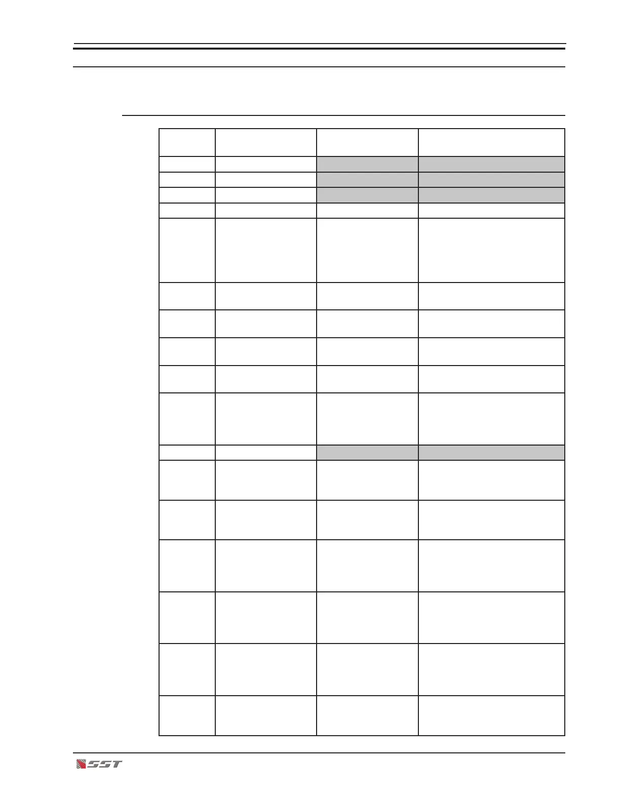
Terminal Connections
Terminal
Number
Marking Connection Description
1 SPARE
2 SPARE
3 SPARE
4 RESET ALARMS Remote Reset Resets Latched Alarm Relays
5 0-20 mA OUTPUT Analog Output Current Source Output
stepped to indicate operating
mode: Ready, Alarm, Delayed
Alarm, Malfunction, Power
Fault
6 LOCAL 0 VDC OUT (-) Power Output Power Source for another
Flame Detector
7 0 VDC IN (-) Power Input To Power Source
16 to 32 volts DC (-)
8 LOCAL +24 VDC
OUT
(+) Power Output Power Source for another
Flame Detector
9 +24 VDC IN (+) Power Input To Power Source
16 to 32 volts DC (+)
10 SURGE GROUND Transient Voltage
Suppressors
Connect direct to Earth
Ground if severe lightning
possible (Otherwise jumper to
terminal 7)
11 SPARE
12 - 13 CLOSED ON FAULT
FAULT RELAY COM
Contact set closes
on loss of power or
detector fault
Fault Relay
Voltage free contact
13 - 14 FAULT RELAY COM
OPEN TO FAULT
Contact set opens
on loss of power or
detector fault
Fault Relay
Voltage free contact
15 - 16 CLOSED ON
DELAY
DELAY RELAY
COM
Contact set closes
when alarm condi-
tion persists for 3 or
6 seconds
Delayed Alarm Relay
Voltage free contact
16 - 17 DELAY RELAY
COM
OPEN ON DELAY
Contact set opens
when alarm
condition persists for
3 or 6 seconds
Delayed Alarm Relay
Voltage free contact
18 - 19 CLOSED ON
ALARM
ALARM RELAY
COM
Contact set closes
when alarm
condition exists
Alarm Relay
Voltage free contact
19 - 20 ALARM RELAY
COM
OPEN ON ALARM
Contact set opens
when alarm
condition exists
Alarm Relay
Voltage free contact
 Loading...