January, 2016 120-49
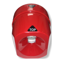
Model F120 UV/IR Flame Detector
REPLACING THE ELECTRONIC MODULE
!
WARNING: Access to the interior of the ame detector or removal of the electronic
module must only be conducted by trained personnel.
!
WARNING: De-classify the area to reduce the risk of ignition of hazardous atmosphere.
Combustible and ammable gases and vapors are very dangerous. Extreme caution
should be taken when these hazards are present.
The ame detector’s electronics module is located within the detector housing. The UV and
two IR sensors are installed on the top board of the electronics module. If any of the sensors
are damaged or non-functional, the entire electronics module must be replaced. Tampering
with the sensors or the electronics module will invalidate the warranty.
Contact the factory to order a new replacement module for the ame detector.
Ordering Information
SST Part # Description
40120-12 Replacement plug-in UV/IR electronics module
!
NOTE: Replacement electronics module is shipped with factory default settings.
Conrm the current settings on your existing electronics module prior to replacement.
Tools Required to Replace the Electronic Module
The following are required to replace the electronic module:
• “4 mm” hex wrench to unlock the set screw on the housing
Steps to Replace the Electronic Module
Disassemble the Detector
1. De-classify the area. Power to the detector can be left on.
2. Use a 4 mm hex wrench to loosen the locking screw on the rear of the detector
housing
3. Unscrew the front housing from the rear housing. Avoid touching the threads of the
front and rear housing. The threads are lubricated. Prevent any contamination (dirt,
etc.) or removal of the lubrication.
4. Remove the electronics module from the rear terminal blocks by gently rocking the
board side-to-side. Place a nger under the top PC board and place another nger
under the edge of this board on the opposite side. Gently rock the board side-to-side
while pulling in order to disengage the module from the rear housing.
!
WARNING: Do not allow dirt or nger marks to get onto the face of the UV or IR
sensors located on the top of the electronics module.