120-20 January, 2016
Model F120 UV/IR Flame Detector
Power
The Model F120 requires a power supply of between 20 VDC and 35 VDC. A minimum
supply of 20 VDC is required at the detector, taking into account the voltage drop due to
cable resistance. Each F120 draws 125 mA continuously from the power supply. Current
draw increases to 230 mA when in alarm.
Wiring Considerations
A minimum of three conductors are required for the power and analog output. Six additional
conductors are required to use the relay contacts. In general, the following rules should be
observed:
• The analog (0-20 mA) cable should be shielded or screened to prevent interference
pickup.
• Avoid running the cable close to high-powered cables or equipment or close to radio
transmitters or antennas.
• Splices should be avoided and connections in junction boxes must be absolutely clean
with terminal screws tight.
Factory Recommended Wires
Use 16 or 18 AWG (1.5 or 0.75 mm2) wires whenever possible.
!
IMPORTANT: Any electrical conduit connected to the F120 enclosure must have a
conduit seal installed within 18 inches (45.7 cm) of the enclosure.
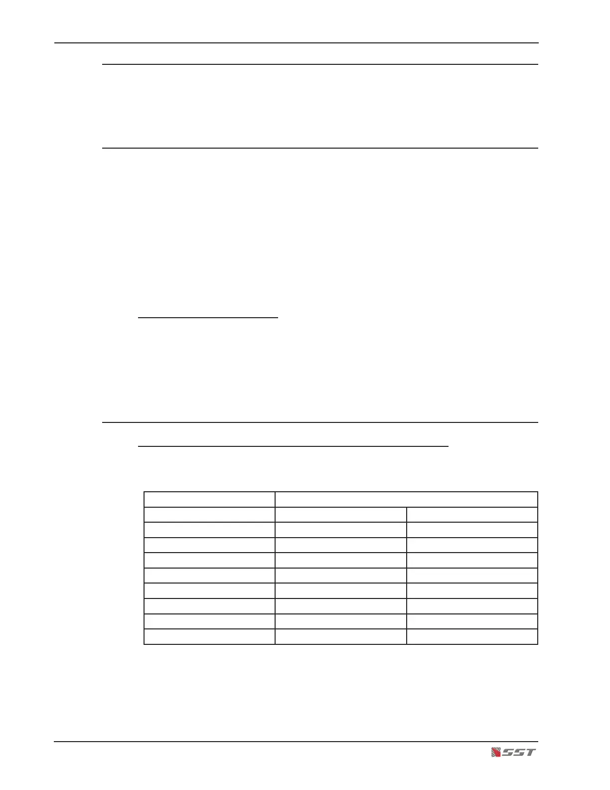
Maximum Cable Lengths
Cable length between 0-20 mA Controller and External Equipment
The total DC resistance of the wires must be less than 800 ohms. The maximum cable
lengths (for 800 ohms) for various wire sizes are listed below:
Maximum Cable Length (L)
Cable Size Feet Meters
26 AWG (.14 mm
2
) 19,043 5,806
24 AWG (.20 mm
2
) 30,288 9,234
22 AWG (.35 mm
2
) 53,530 16,320
20 AWG (0.5 mm
2
) 78,270 23,863
18 AWG (1.0 mm
2
) 145,295 44,297
16 AWG (1.5 mm
2
) 200,624 61,166
14 AWG (2.5 mm
2
) 317,879 96,914
12 AWG (4.0 mm
2
) 499,310 152,229