120-24 January, 2016
Model F120 UV/IR Flame Detector
5. Pull the wires through the conduit and out through the rear housing.
4-B. Install the Wall/Ceiling Mounting Bracket
For Cable Gland Installation
1. Install the Wall/Ceiling Mounting Bracket at the desired location. The mounting
bracket has a square mounting base for solid surfaces, 2.5” x 2.5” (63.5mm x
63.5mm), with four 0.219” (5.56mm) holes on 2.0” (50.8mm) x 2.0” (50.8 mm) layout.
Use four #10 or M5 screws. Screws are not included.
2. Apply the supplied thread locking adhesive to the threaded stud on the end of the
swivel bracket. Also apply the thread locker to the mating tapped hole on the rear of
the ame detector.
!
IMPORTANT: Apply the adhesive to the threaded stud on the end of the swivel bracket
and the mating tapped hole on the rear of the ame detector. If locker is only applied
to the stud, air pressure will force the liquid thread locker to escape as you torque
it down. Lack of uniform coverage creates air pockets, causing incomplete adhesive
cures which may result in the bracket coming loose from the ame detector.
3. Insert the threaded stud into the tapped hole on the rear housing and hand tight ONLY.
The thread locker will cure in 10 minutes at room temperature, and at that time it will
be acceptable to carefully continue with the installation. Full strength thread bonding
will occur after 24 hours.
!
IMPORTANT: Do not use any tools to tighten the threaded stud into the tapped hole
on the rear housing. The detector housing is cast aluminum; excessive tightening
will strip the aluminum threads.
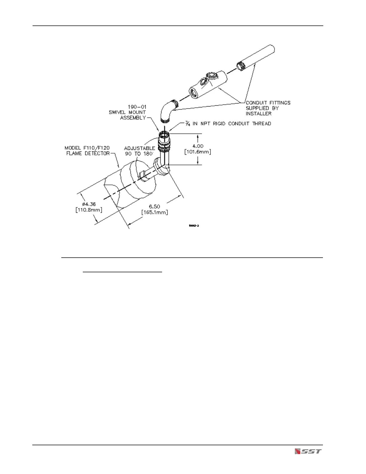
Conduit Mounting Assembly