January, 2016 120-35
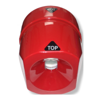
Model F120 UV/IR Flame Detector
12. Apply Power
!
WARNING: Verify that there are NO combustible gases present before power to the
ame detector is turned on.
Power can be applied for the rst time, when the rear housing has been properly mounted,
wired, tested, and the electronics module is in place and the front housing sufciently tightened
onto and aligned with the rear housing.
!
WARNING: DO NOT TOUCH any part of the electronics module when power is on.
Voltages in excess of 300 volts DC are present on the electronics module.
Warm-up
On power up, the detector goes through a “warm-up” sequence. Initially, the green, yellow,
and red LEDs are activated for 1 second each. Then the green LED ashes for the remainder
of the warm-up period, approximately 3 minutes.
When the green LED changes to a steady ON condition, the detector in is normal operation.
Automatic Self-Check (ASC)
Ten seconds after warm-up is complete, and every 10 seconds thereafter, the green LED
will remain “ON” and the detector will enter the Automatic Self-Check (ASC) mode. The
test lamp is activated, and the electronic circuits are checked. Please note that the test
lamp signal is not visible to the naked eye during this test.
A single green LED displayed at the end of the ASC indicates a “pass” condition.
A yellow LED indicates a fault (malfunction) condition.
If the ame detector signals a malfunction, check to make sure that the front and rear
housings are sufciently engaged and that the aligning notches and aligning screw is in
position.
Additional troubleshooting instructions can be found in the Troubleshooting Section of this
manual.