120-46 January, 2016
Model F120 UV/IR Flame Detector
Steps to Change the Detection Mode
!
WARNING: Access to the interior of the ame detector or removal of the electronics
module must only be conducted by trained personnel.
!
WARNING: De-classify the area to reduce the risk of ignition of hazardous atmosphere.
Combustible and ammable gases and vapors are very dangerous. Extreme caution
should be taken when these hazards are present.
Disassemble the Detector
1. De-classify the area. Power to the detector can be left on.
2. Use a 4 mm hex wrench to loosen the locking screw on the rear of the detector
housing
3. Unscrew the front housing from the rear housing. Avoid touching the threads of the
front and rear housing. The threads are lubricated. Prevent any contamination (dirt,
etc.) or removal of the lubrication.
4. Remove the electronics module from the rear terminal blocks by gently rocking the
board side-to-side. Place a nger under the top PC board and place another nger
under the edge of this board on the opposite side. Gently rock the board side-to-side
while pulling in order to disengage the module from the rear housing.
!
WARNING: Do not allow dirt or nger marks to get onto the face of the UV or IR
sensors located on the top of the electronics module.
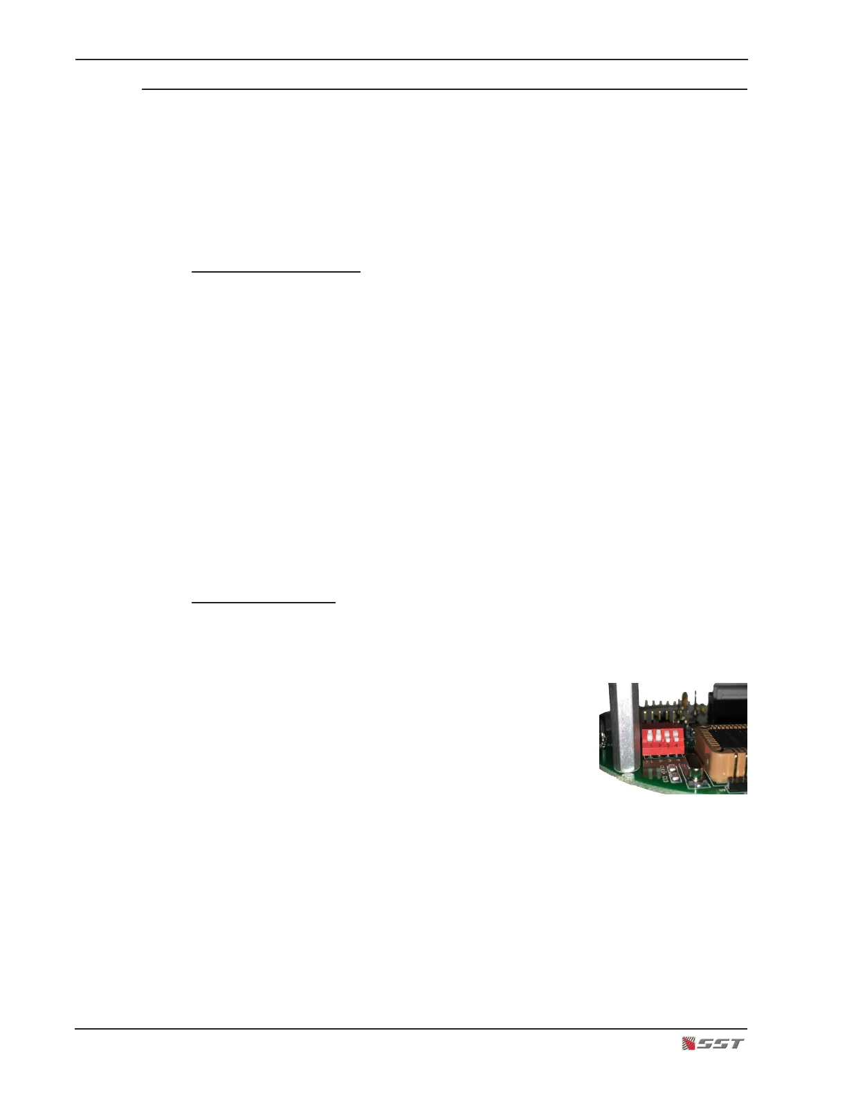
Locate the DIP Switch
The DIP Switch is located on the underside of the upper board in the electronics module. Turn
the electronics module upside down to easily view the switch, being careful not to disturb the
3 sensors. Switches #1 and #2 sets the operational mode of the detector.
There are four switch sections; these are identied by
the numbers 1 through 4 marked on the printed circuit
board next to the switch.
The units are manufactured with switches that have
the operating mechanism on the side of the switch, as
shown in the picture. With this type of switch, which
can be set in the UP or DOWN position, use the instruc-
tions below to set the switches.