120-30 January, 2016
Model F120 UV/IR Flame Detector
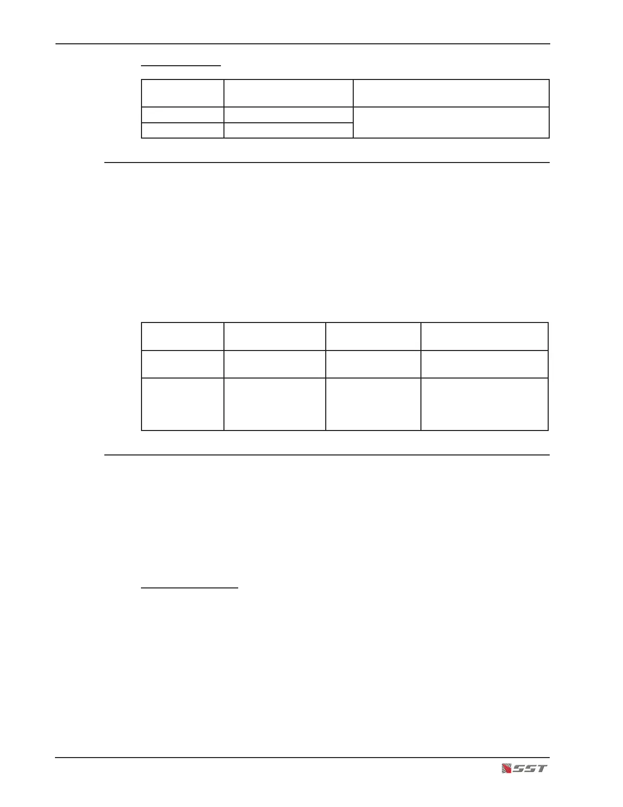
Normally Closed
Terminal
Number
Marking Connection
13 FAULT RELAY COM Contacts set to Normally Closed and
Open on Fault
14 OPEN ON FAULT
6. Connect the Detector to Earth Ground
A Ground Terminal is provided on both the inside and outside walls of the rear housing for
use in applications where the conduit does not provide adequate grounding to the F120, or
the System Designer determines that additional grounding is required.
A minimum 18 AWG (0.75 mm
2
) wire is required for ground connection.
Circuitry that protects against damage from lightning, miscellaneous transients and power
surges are internally connected to terminal # 10 on the terminal block. As shipped from the
factory, a jumper wire is installed between rear terminal # 10 and the 0 volt terminal #7, thus
connecting the transient protection to the grounded 0 volt power line. The 0 volt power line
must always be grounded, either at the F120 or elsewhere in the system.
Terminal
Number
Marking Connection Description
7 0 VDC IN (-) Power Input To Power Source
16 to 32 volts DC (-)
10 SURGE GROUND Transient Voltage
Suppressors
Connect direct to Earth
Ground if severe lightning
possible (Otherwise
jumper to terminal 7)
7. Set the Detection Mode DIP Switch
The ame detector has 4 operational modes of detection:
1. Triple-mode UV/IR
2. UV Only Mode
3. Dual IR Mode
4. IR Mode
DIP Switch Location
The DIP Switch is located on the underside of the upper board in the electronics module. Turn
the electronics module upside down to easily view the switch, being careful not to disturb the
3 sensors. Switches #1 and #2 sets the operational mode of the detector.
There are four switch sections; these are identied by the numbers 1 through 4 marked on
the printed circuit board next to the switch.
The units are manufactured with switches that have the operating mechanism on the side
of the switch, as shown in the picture. With this type of switch, which can be set in the UP
or DOWN position, use the instructions below to set the switches.

 Loading...