January, 2016 120-55
Model F120 UV/IR Flame Detector
Ordering Information
SST Part # Description
40110-21 Replacement self-test lamp with ring-type PC board
!
IMPORTANT: Never touch the lamp with your ngers. Use caution when handling
the replacement self-test lamp. Do not touch or bend the test lamp.
Tools Required to Replace the Electronic Module
The following are required to replace the electronic module:
• “4 mm” hex wrench to unlock the set screw on the housing
Steps to Replace the Self-Test Lamp Electronic Module
Disassemble the Detector
1. De-classify the area. Power to the detector can be left on.
2. Use a 4 mm hex wrench to loosen the locking screw on the rear of the detector
housing
3. Unscrew the front housing from the rear housing. Avoid touching the threads of the
front and rear housing. The threads are lubricated. Prevent any contamination (dirt,
etc.) or removal of the lubrication.
4. Set aside the rear housing with the electronics module still attached.
!
WARNING: Do not allow dirt or nger marks to get onto the face of the UV or IR
sensors located on the top of the electronics module.
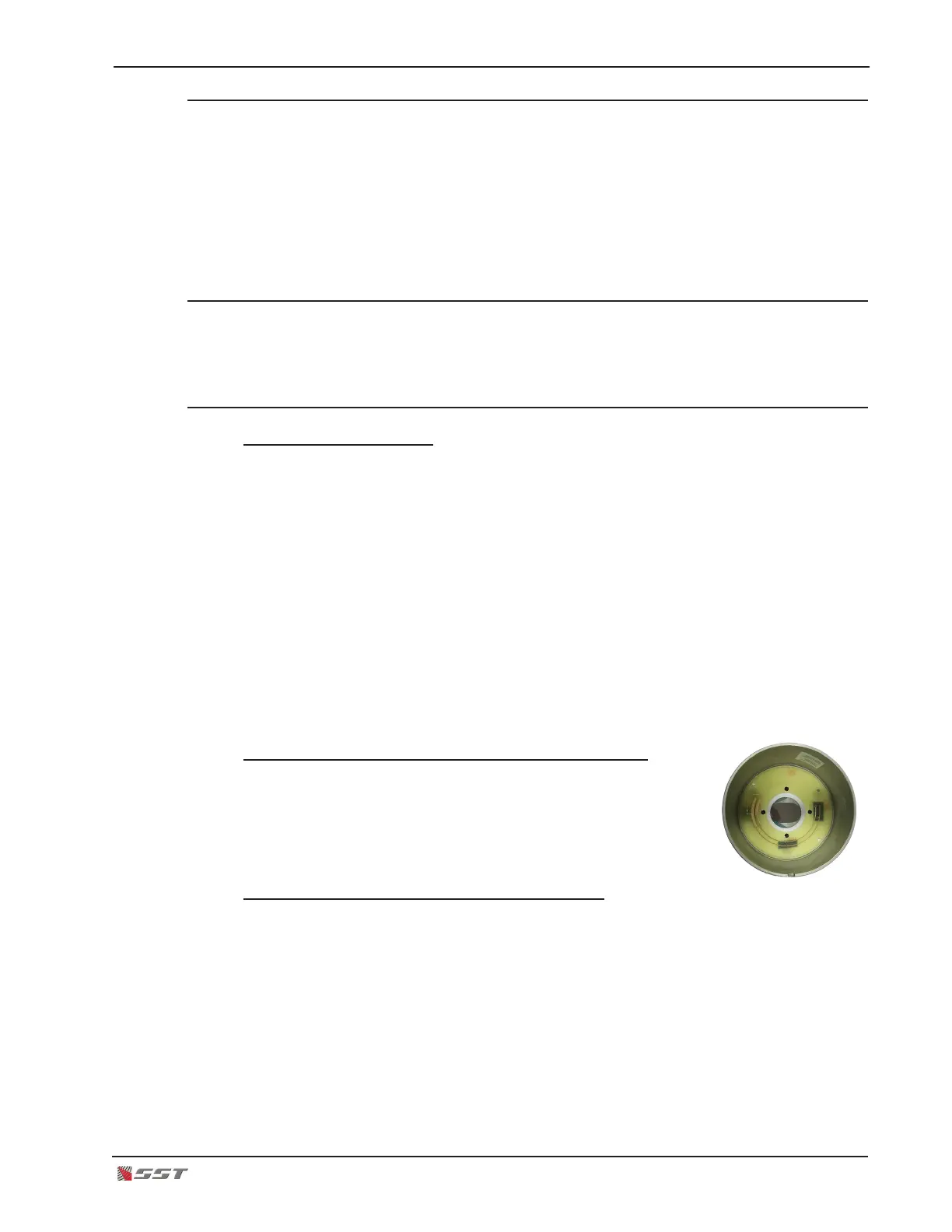
Remove the Existing Self-Test Lamp Electronics Board
5. Inside the front housing, the self-test lamp electronics module
can be seen attached with four screws.
6. Unscrew the four screws and gently remove the self-test lamp
electronics board from the front housing.
Install the New Self-Test Lamp Electronics Board
7. Handle the new self-test lamp electronics board gently by holding it around the
electronics board. DO NOT touch the test lamp with your bare ngers.
8. Position the test lamp into the orice of the front housing and gently insert. The four
screw holes on the electronics board should match with the holes on the front housing.
9. Secure the electronics board in place by using the four new screws supplied and
attach the electronics board on the front housing. Use a small phillips screwdriver and
hand tighten only. DO NOT use any power tools as it may damage the electronics
board and the housing.