120-22 January, 2016
Model F120 UV/IR Flame Detector
INSTALLATION
1. Shipment
Flame detectors shipped by Safety Systems Technology is fully assembled, quality tested
and packaged in special containers to protect against physical damage.
Upon receipt of the shipment, contents should be carefully removed and checked against the
packing list. Contact Safety Systems Technology immediately if any damage has occurred
or if there is any discrepancy in the order.
2. Tools Required
• 4 mm hex wrench to remove the enclosure cover
• Flat-head screwdriver maximum 3/16” (5 mm) width for terminal block connections
• Adjustable wrench for conduit or cable gland connections
• Multi-meter to verify power
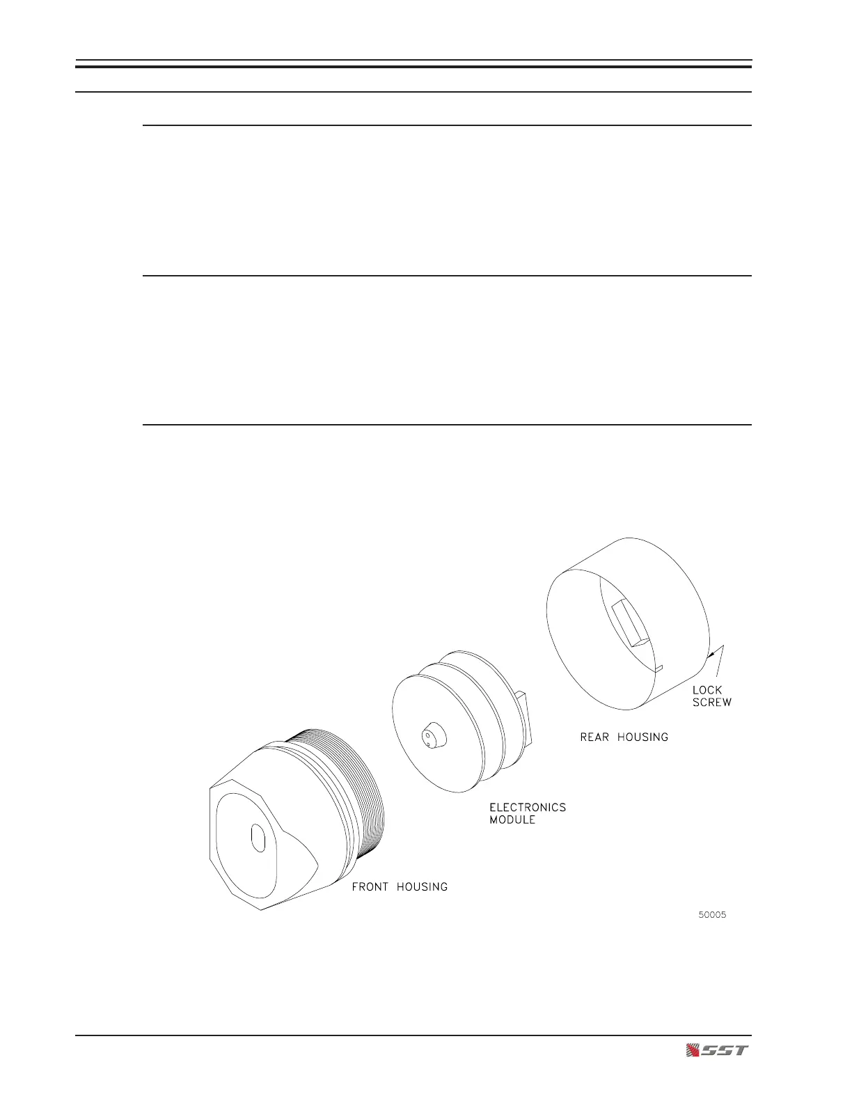
3. Disassemble the Detector
Before installing the detector, you must disassemble the unit into three components shown
below.

 Loading...