January, 2016 120-47
Model F120 UV/IR Flame Detector
Changing the Detection Mode
5. To change the detection mode of the ame detector, follow the table below to adjust
the DIP Switch settings. Please note that the factory default setting for the ame
detector is set to Triple-mode.
Switch # 1 Switch # 2 Description
UP UP Triple-mode UV/IR detection, voted any two out
of three sensors (Default Setting)
UP DOWN UV Only
DOWN DOWN Dual IR (IR/IR)
DOWN UP IR Flicker Only
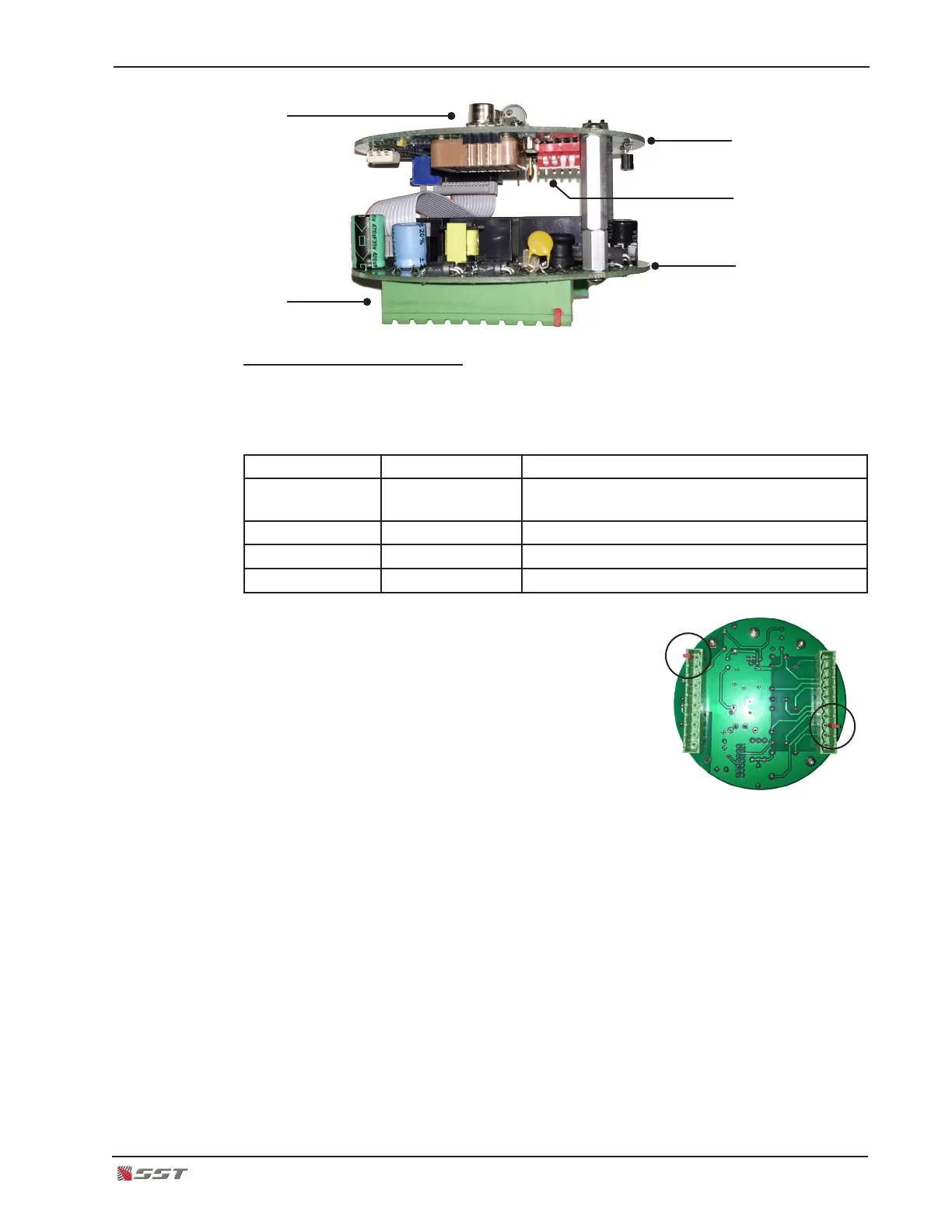
6. Connect polarized terminal blocks.
The mating terminal blocks of the electronics module
and the rear housing each have protective (RED) polar-
izing keys. This key is used to protect against improper
mating of the terminal blocks.
!
CAUTION: The RED key of the Electronics Module
WILL NOT FIT over the Red Key of the rear housing
connector. Orient the electronics module so that the Red Keys are NOT aligned.
Do not force the electronics module or damage may occur to the terminal blocks.
7. Plug the electronics module.
8. Secure the electronics module in place by placing a thumb over each screw head on
the top PC board of the electronics module and gently push the electronics module in
place. Make sure the module is rmly secured on the rear housing terminal blocks.
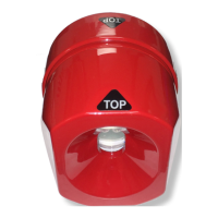
UV/IR Sensors
Terminal Blocks
Top Board
Bottom Board
DIP Switch