120-50 January, 2016
Model F120 UV/IR Flame Detector
Modify the Settings on the New Module
5. Conrm the settings from the old electronics module and copy the settings on the new
electronics module.
Locate the DIP Switch
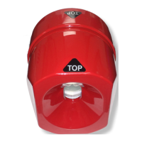
6. The DIP Switch is located on the underside of the upper board in the electronics
module. Turn the electronics module upside down to easily view the switch, being
careful not to disturb the 3 sensors. Switches #1 and #2 sets the operational mode of
the detector.
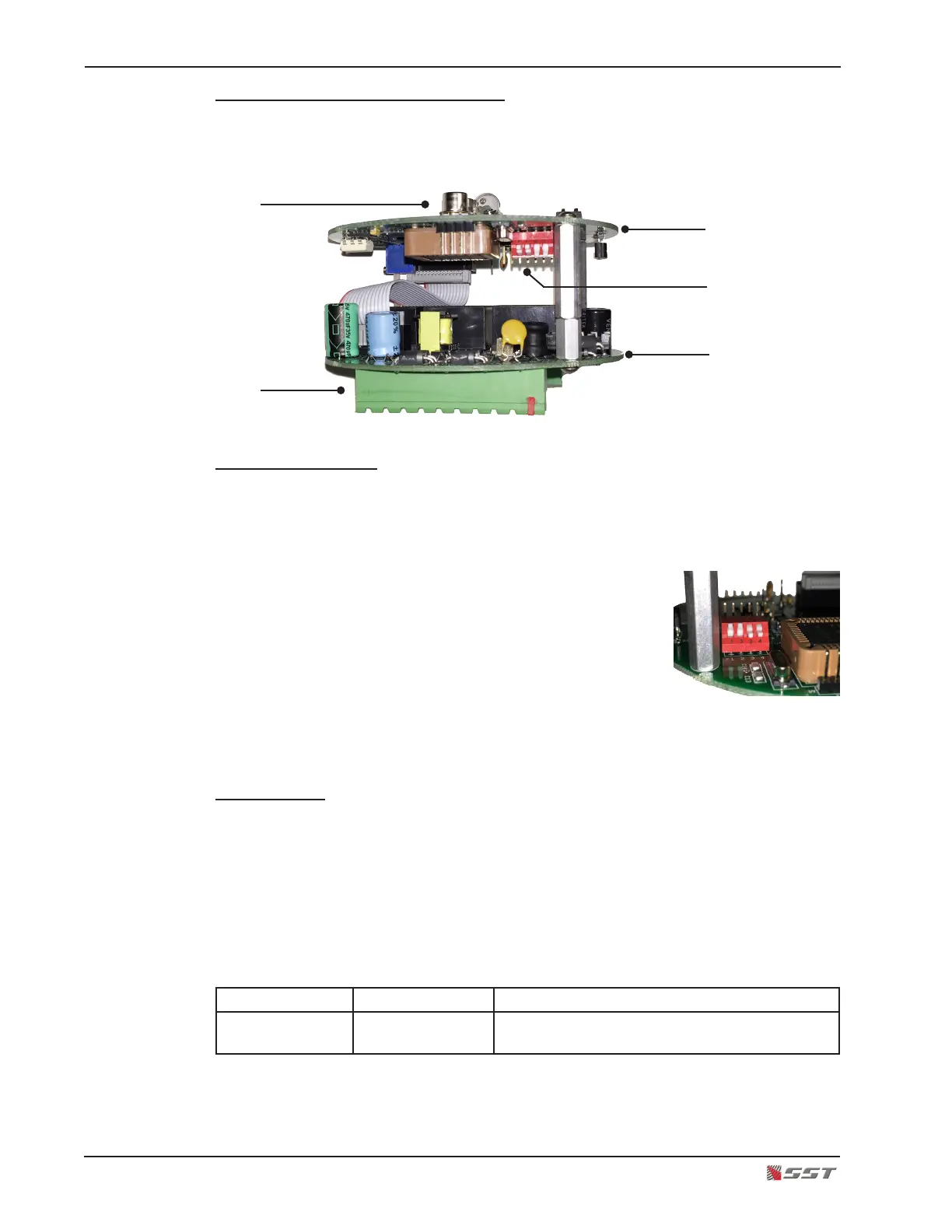
There are four switch sections; these are identied by
the numbers 1 through 4 marked on the printed circuit
board next to the switch.
The units are manufactured with switches that have
the operating mechanism on the side of the switch, as
shown in the picture. With this type of switch, which can
be set in the UP or DOWN position, use the instructions
below to set the switches.
Default Setting
The factory default setting for the ame detector’s operational mode is “Triple-mode” - the one
UV sensor and two IR sensors are activated and for the detector to signal an Alarm condition,
the detector uses a voting logic where a minimum of two out of the three sensors reports a re.
Conrm that the Default Setting for the ame detector is set to Triple-mode. The UP position
means that the switch is moved to the upper position, farthermost from the printed circuit
board. The DOWN position means that the switch is moved to the lower position or closest
to the printed circuit board.
Switch # 1 Switch # 2 Description
UP UP Triple-mode UV/IR detection, voted any two out
of three sensors
UV/IR Sensors
Terminal Blocks
Top Board
Bottom Board
DIP Switch