January, 2016 120-3
Model F120 UV/IR Flame Detector
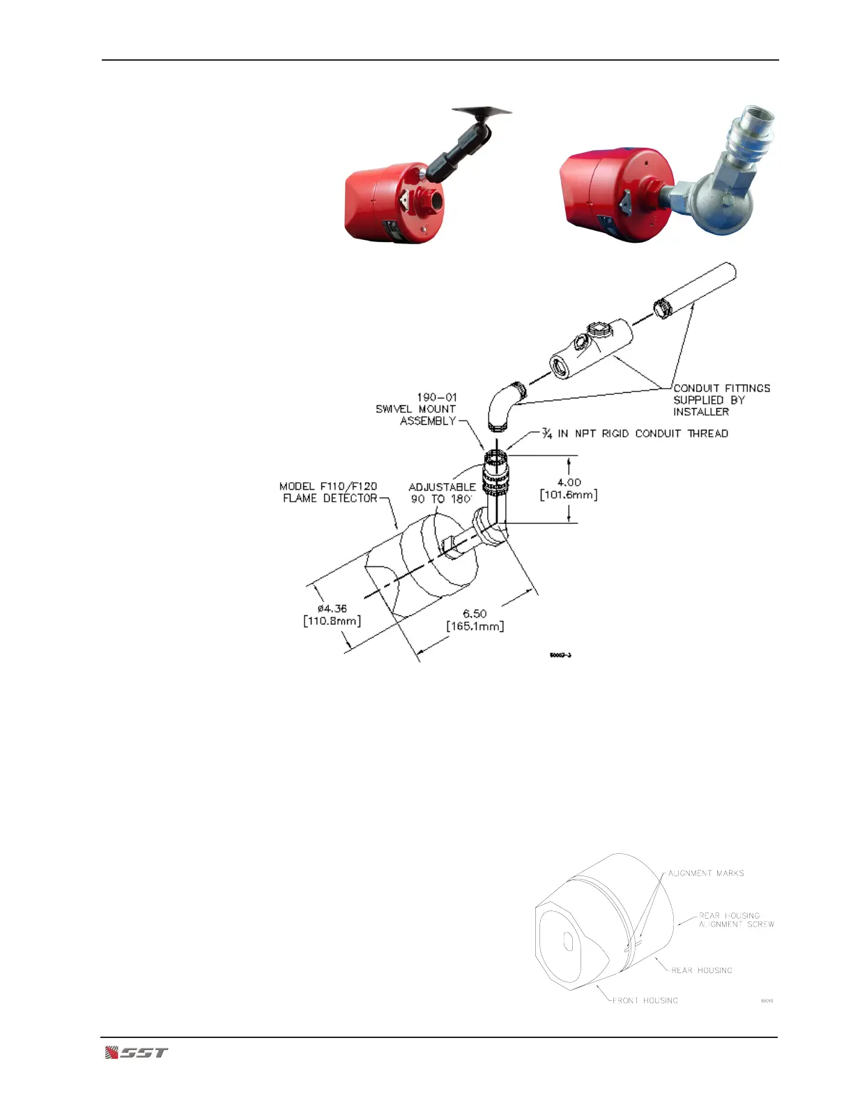
Wall or Ceiling Mounting Bracket Conduit Mounting Bracket
Conduit Mounting Assembly
4. Run the wires through the rear housing conduit opening of the ame detector
5. Wire and connect the detector to earth ground (see Wiring Diagrams on next pages)
6. Plug the electronics module
Note that the terminal blocks of the electronics module and rear housing each have
protective (RED) polarizing keys. Orient so that the Red Keys on the electronics are
NOT aligned with the Red Keys on the terminal blocks.
7. Screw the front housing to the rear
housing, hand tight only
8. Align the “aligning marks” on the front
and rear housing.
9. Apply power
10. Perform Final Operational Checkout per
Design Manual
11. Install accessories, if any