PM0214 Rev 10 63/262
PM0214 The STM32 Cortex-M4 instruction set
261
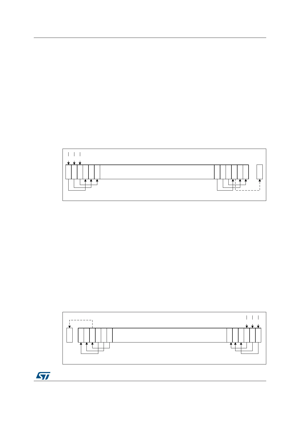
LSR
Logical shift right by n bits moves the left-hand 32-n bits of the Rm register to the right by n
places, into the right-hand 32-n bits of the result. And it sets the left-hand n bits of the result
to 0 (see Figure 14).
You can use the LSR #n operation to divide the value in the Rm register by 2
n
, if the value is
regarded as an unsigned integer.
When the instruction is LSRS or when LSR #n is used in operand2 with the instructions
MOVS, MVNS, ANDS, ORRS, ORNS, EORS, BICS, TEQ or TST, the carry flag is updated
to the last bit shifted out, bit[n-1], of the Rm register.
Note: 1 If n is 32 or more, then all the bits in the result are cleared to 0.
2 If n is 33 or more and the carry flag is updated, it is updated to 0.
Figure 14. LSR #3
LSL
Logical shift left by n bits moves the right-hand 32-n bits of the Rm register to the left by n
places, into the left-hand 32-n bits of the result. And it sets the right-hand n bits of the result
to 0 (see Figure 15: LSL #3).
The LSL #n operation can be used to multiply the value in the Rm register by 2
n
, if the value
is regarded as an unsigned integer or a two’s complement signed integer. Overflow can
occur without warning.
When the instruction is LSLS or when LSL #n, with non-zero n, is used in operand2 with the
instructions MOVS, MVNS, ANDS, ORRS, ORNS, EORS, BICS, TEQ or TST, the carry flag
is updated to the last bit shifted out, bit[32-n], of the Rm register. These instructions do not
affect the carry flag when used with LSL #0.
Note: 1 If n is 32 or more, then all the bits in the result are cleared to 0.
2 If n is 33 or more and the carry flag is updated, it is updated to 0.
Figure 15. LSL #3
MSv39679V1
Carry
Flag
031 5 4 3 2 1
00
0
MSv39678V1
031 5 4 3 2 1
Carry
Flag
00
0
 Loading...


