Advanced-control timers (TIM1/TIM8/TIM20) RM0440
1106/2126 RM0440 Rev 4
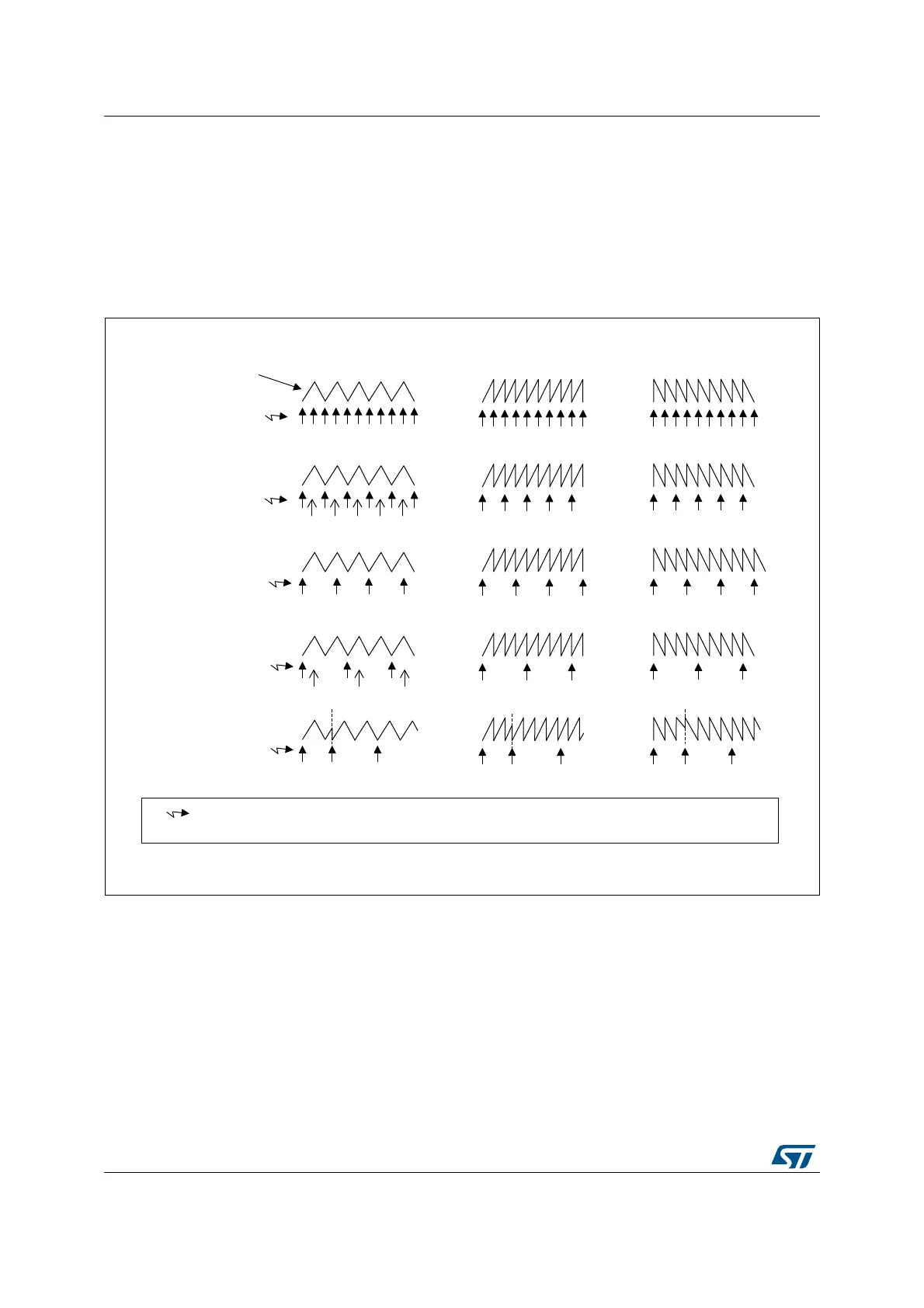
In Center aligned mode, for odd values of RCR, the update event occurs either on the
overflow or on the underflow depending on when the RCR register was written and when
the counter was launched: if the RCR was written before launching the counter, the UEV
occurs on the underflow. If the RCR was written after launching the counter, the UEV occurs
on the overflow.
For example, for RCR = 3, the UEV is generated each 4th overflow or underflow event
depending on when the RCR was written.
Figure 289. Update rate examples depending on mode and TIMx_RCR register settings
28.3.6 External trigger input
The timer features an external trigger input tim_etr_in. It can be used as:
• external clock (external clock mode 2, see Section 28.3.7)
• trigger for the slave mode (see Section 28.3.30)
• PWM reset input for cycle-by-cycle current regulation (see Section 28.3.9)
Figure 290 below describes the tim_etr_in input conditioning. The input polarity is defined
with the ETP bit in TIMxSMCR register. The trigger can be prescaled with the divider
programmed by the ETPS[1:0] bitfield and digitally filtered with the ETF[3:0] bitfield. The
resulting signal (tim_etrf) is available for three purposes: as an external clock, to condition
MSv31195V1
UEV
UEV
UEV
UEV
UEV
Counter-aligned mode
Edge-aligned mode
Upcounting Downcounting
(by SW)(by SW)(by SW)
TIMx_RCR = 3
and
re-synchronization
TIMx_RCR = 3
TIMx_RCR = 2
TIMx_RCR = 1
TIMx_RCR = 0
Counter
TIMx_CNT
UEV
Update event: Preload registers transferred to active registers and update interrupt generated
Update Event if the repetition counter underflow occurs when the counter is equal to the auto-reload value.

 Loading...


