RM0440 Rev 4 1629/2126
RM0440 Universal synchronous/asynchronous receiver transmitter (USART/UART)
1733
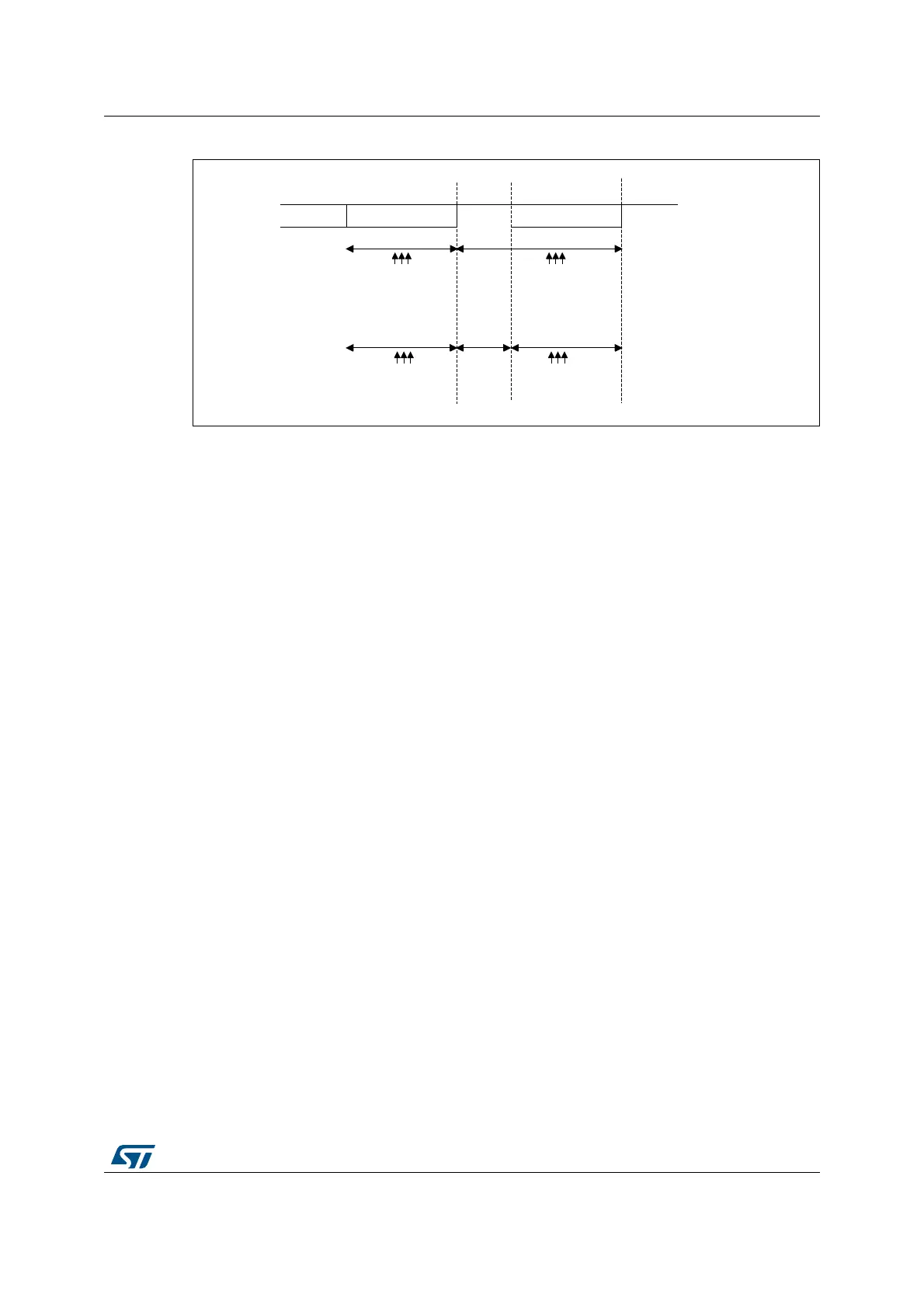
Figure 547. Parity error detection using the 1.5 stop bits
The USART can provide a clock to the Smartcard through the SCLK output. In Smartcard
mode, SCLK is not associated to the communication but is simply derived from the internal
peripheral input clock through a 5-bit prescaler. The division ratio is configured in the
USART_GTPR register. SCLK frequency can be programmed from usart_ker_ck_pres/2 to
usart_ker_ck_pres/62, where usart_ker_ck_pres is the peripheral input clock divided by a
programmed prescaler.
Block mode (T=1)
In T=1 (block) mode, the parity error transmission can be deactivated by clearing the NACK
bit in the USART_CR3 register.
When requesting a read from the Smartcard, in block mode, the software must program the
RTOR register to the BWT (block wait time) - 11 value. If no answer is received from the
card before the expiration of this period, a timeout interrupt is generated. If the first
character is received before the expiration of the period, it is signaled by the RXNE/RXFNE
interrupt.
Note: The RXNE/RXFNE interrupt must be enabled even when using the USART in DMA mode to
read from the Smartcard in block mode. In parallel, the DMA must be enabled only after the
first received byte.
After the reception of the first character (RXNE/RXFNE interrupt), the RTO register must be
programmed to the CWT (character wait time -11 value), in order to enable the automatic
check of the maximum wait time between two consecutive characters. This time is
expressed in baud time units. If the Smartcard does not send a new character in less than
the CWT period after the end of the previous character, the USART signals it to the software
through the RTOF flag and interrupt (when RTOIE bit is set).
Note: As in the Smartcard protocol definition, the BWT/CWT values should be defined from the
beginning (start bit) of the last character. The RTO register must be programmed to BWT -
11 or CWT -11, respectively, taking into account the length of the last character itself.
A block length counter is used to count all the characters received by the USART. This
counter is reset when the USART is transmitting. The length of the block is communicated
by the Smartcard in the third byte of the block (prologue field). This value must be
programmed to the BLEN field in the USART_RTOR register. When using DMA mode,
before the start of the block, this register field must be programmed to the minimum value
MSv31163V1
Bit 7
Parity bit
1.5 Stop bit
1 bit time 1.5 bit time
0.5 bit time
Sampling at
8th, 9th, 10th
Sampling at
8th, 9th, 10th
Sampling at
8th, 9th, 10th
Sampling at
8th, 9th, 10th

 Loading...


