AES hardware accelerator (AES) RM0440
1506/2126 RM0440 Rev 4
34.4.9 AES counter (CTR) mode
Overview
The counter mode (CTR) uses AES as a key-stream generator. The generated keys are
then XOR-ed with the plaintext to obtain the ciphertext.
CTR chaining is defined in NIST Special Publication 800-38A, Recommendation for Block
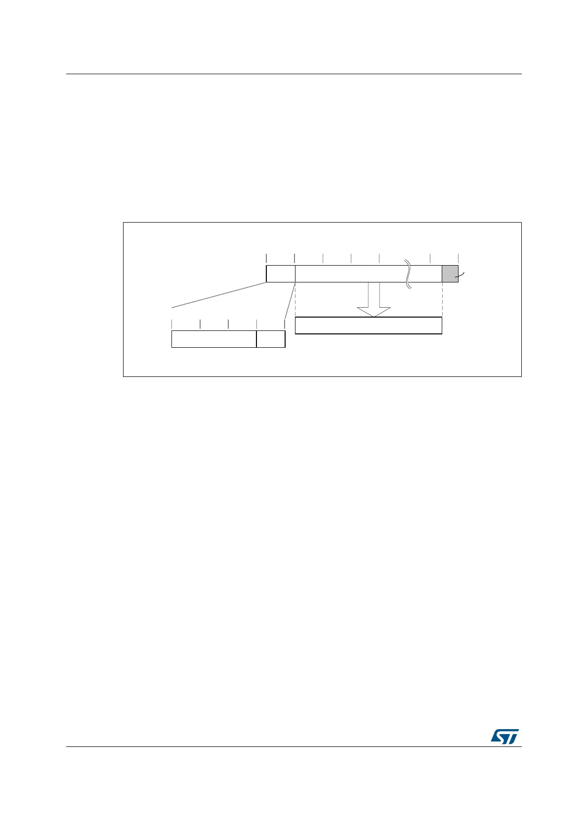
Cipher Modes of Operation. A typical message construction in CTR mode is given in
Figure 516.
Figure 516. Message construction in CTR mode
The structure of this message is:
• A 16-byte initial counter block (ICB), composed of two distinct fields:
– Initialization vector (IV): a 96-bit value that must be unique for each encryption
cycle with a given key.
– Counter: a 32-bit big-endian integer that is incremented each time a block
processing is completed. The initial value of the counter should be set to 1.
• The plaintext P is encrypted as ciphertext C, with a known length. This length can be
non-multiple of 16 bytes, in which case a plaintext padding is required.
CTR encryption and decryption
Figure 517 and Figure 518 describe the CTR encryption and decryption process,
respectively, as implemented in the AES peripheral. The CTR mode is selected by writing
010 to the CHMOD[2:0] bitfield of AES_CR register.
MSv42156V1
16-byte boundaries
ICB Ciphertext (C) 0
4-byte boundaries
CounterInitialization vector (IV)
decrypt
Plaintext (P)
Zero
padding

 Loading...


