Advanced-control timers (TIM1/TIM8/TIM20) RM0440
1168/2126 RM0440 Rev 4
In the following example, the upcounter is cleared in response to a rising edge on tim_ti1
input:
• Configure the channel 1 to detect rising edges on tim_ti1. Configure the input filter
duration (in this example, we do not need any filter, so we keep IC1F=0000). The
capture prescaler is not used for triggering, so it does not need to be configured. The
CC1S bits select the input capture source only, CC1S = 01 in the TIMx_CCMR1
register. Write CC1P=0 and CC1NP=’0’ in TIMx_CCER register to validate the polarity
(and detect rising edges only).
• Configure the timer in reset mode by writing SMS=100 in TIMx_SMCR register. Select
tim_ti1 as the input source by writing TS=00101 in TIMx_SMCR register.
• Start the counter by writing CEN=1 in the TIMx_CR1 register.
The counter starts counting on the internal clock, then behaves normally until tim_ti1 rising
edge. When tim_ti1 rises, the counter is cleared and restarts from 0. In the meantime, the
trigger flag is set (TIF bit in the TIMx_SR register) and an interrupt request, or a DMA
request can be sent if enabled (depending on the TIE and TDE bits in TIMx_DIER register).
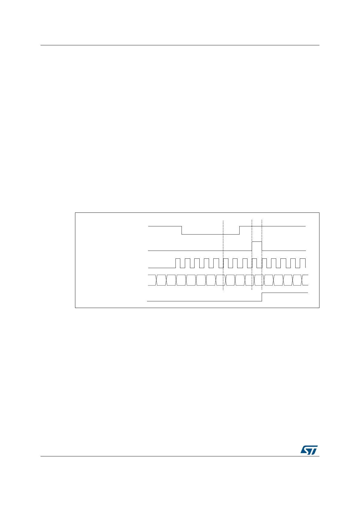
The following figure shows this behavior when the auto-reload register TIMx_ARR=0x36.
The delay between the rising edge on tim_ti1 and the actual reset of the counter is due to
the resynchronization circuit on tim_ti1 input.
Figure 354. Control circuit in reset mode
Slave mode: Gated mode
The counter can be enabled depending on the level of a selected input.
In the following example, the upcounter counts only when tim_ti1 input is low:
• Configure the channel 1 to detect low levels on tim_ti1. Configure the input filter
duration (in this example, we do not need any filter, so we keep IC1F=0000). The
capture prescaler is not used for triggering, so it does not need to be configured. The
CC1S bits select the input capture source only, CC1S=01 in TIMx_CCMR1 register.
Write CC1P=1 and CC1NP=’0’ in TIMx_CCER register to validate the polarity (and
detect low level only).
• Configure the timer in gated mode by writing SMS=101 in TIMx_SMCR register. Select
tim_ti1 as the input source by writing TS=00101 in TIMx_SMCR register.
• Enable the counter by writing CEN=1 in the TIMx_CR1 register (in gated mode, the
counter doesn’t start if CEN=0, whatever is the trigger input level).
MSv62361V1
00
tim_cnt_ck, tim_psc_ck
Counter register
01 02 03 00 01 02 0332 33 34 35 36
UG
tim_ti1
3130
TIF

 Loading...


