Serial audio interface (SAI) RM0440
1822/2126 RM0440 Rev 4
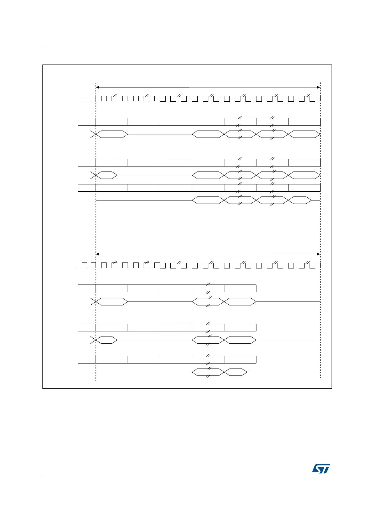
Figure 625. Tristate strategy on SD output line on an inactive slot
When the selected audio protocol uses the FS signal as a start of frame and a channel side
identification (bit FSDEF = 1 in the SAI_xFRCR register), the tristate mode is managed
according to Figure 626 (where bit TRIS in the SAI_xCR1 register = 1, and FSDEF=1, and
half frame length is higher than number of slots/2, and NBSLOT=6).
slot
Audio frame
Bit TRIS = 1 in the SAI_xCR1 and frame length = number of slots
MS192345V1
Slot size = data size
Slot size > data size
Bit TRIS = 1 in the SAI_xCR1 and frame length > number of slots
SD (output)
sck
Slot 0 ON Slot 1 OFF
Slot 2 OFF Slot 3 ON .. ON .. ON Slot n ON
Data 0 Data 1 .. .. Data m
Slot 0 ON Slot 1 OFF
Slot 2 OFF Slot 3 ON .. ON .. ON Slot n ON
Data 0
Data 1 .. .. Data m
Slot 0 ON Slot 1 OFF
Slot 2 OFF Slot 3 ON .. ON .. ON Slot n ON
Data 0 .. .. Data m
slot
SD (output)
slot
SD (output)
slot
Audio frame
Slot size = data size
SD (output)
sck
Slot 0 ON Slot 1 OFF
Slot 2 OFF .. ON Slot n ON
Data 0 .. Data m
slot
Slot size > data size
SD (output)
Slot 0 ON Slot 1 OFF
Slot 2 OFF .. ON Slot n ON
.. Data m
Data 0
slot
SD (output)
Slot 0 ON Slot 1 OFF
Slot 2 OFF .. ON
..
Data m
.. ON

 Loading...


