Advanced-control timers (TIM1/TIM8/TIM20) RM0440
1120/2126 RM0440 Rev 4
in the TIMx_CR1 register. Moreover, the DIR and CMS bits must not be changed at the
same time by the software.
• Writing to the counter while running in center-aligned mode is not recommended as it
can lead to unexpected results. In particular:
– The direction is not updated if a value greater than the auto-reload value is written
in the counter (TIMx_CNT > TIMx_ARR). For example, if the counter was counting
up, it continues to count up.
– The direction is updated if 0 or the TIMx_ARR value is written in the counter but no
Update Event UEV is generated.
• The safest way to use center-aligned mode is to generate an update by software
(setting the UG bit in the TIMx_EGR register) just before starting the counter and not to
write the counter while it is running.
Dithering mode
The PWM mode effective resolution can be increased by enabling the dithering mode, using
the DITHEN bit in the TIMx_CR1 register. This applies to both the CCR (for duty cycle
resolution increase) and ARR (for PWM frequency resolution increase).
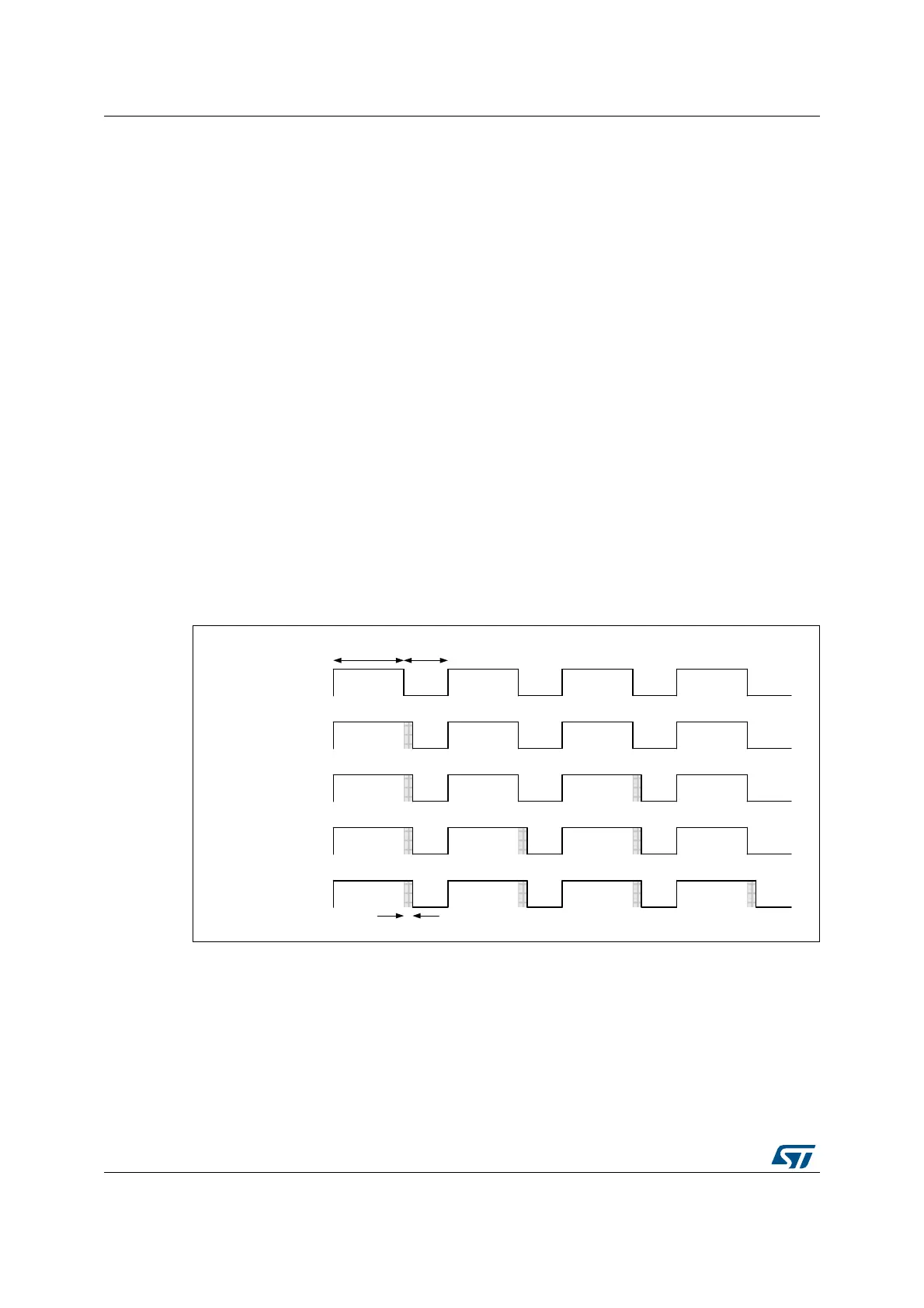
The operating principle is to have the actual CCR (or ARR) value slightly changed (adding
or not one timer clock period) over 16 consecutive PWM periods, with predefined patterns.
This allows a 16-fold resolution increase, considering the average duty cycle or PWM
period. The Figure 304 below presents the dithering principle applied to 4 consecutive PWM
cycles.
Figure 304. Dithering principle
When the dithering mode is enabled, the register coding is changed as follows (see
Figure 305 for example):
• the 4 LSBs are coding for the enhanced resolution part (fractional part)
• The MSBs are left-shifted to the bits 19:4 and are coding for the base value
Note: The ARR and CCR values will be updated automatically if the DITHEN bit is set / reset (for
instance, if ARR= 0x05 with DITHEN=0, it will be updated to ARR = 0x50 with DITHEN=1).
The following sequence must be followed when resetting the DITHEN bit:
1. CEN and ARPE bits must be reset
MSv45752V1
1 clock cycle
Average duty cycle
75
DC = 7/5
DC = (7+¼)/5
DC = (7+½)/5
DC = (7+¾)/5
DC = 8/5

 Loading...


