82 GS 461
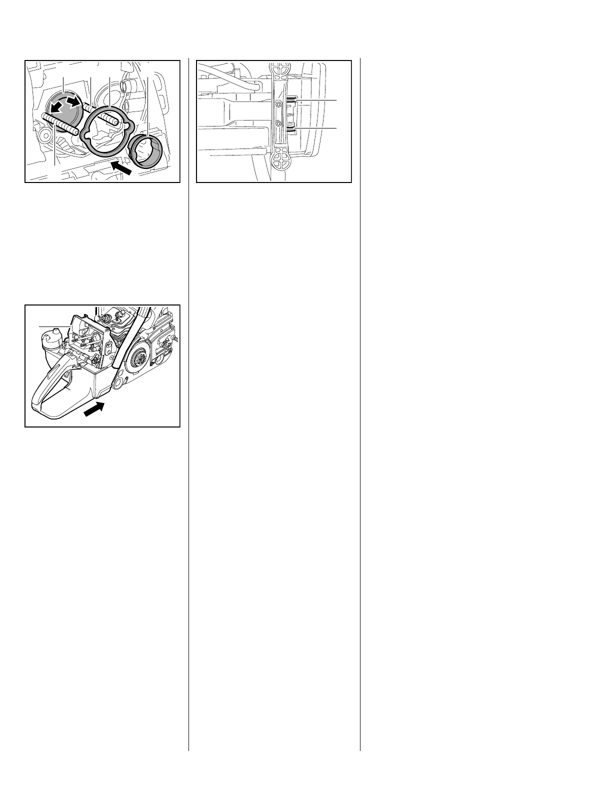
: Orient the manifold flange (1), –
the openings (arrows) must rest
against the studs (2)
: Fit washer (3) and push
sleeve (4) into the opening of the
manifold flange (1)
: Press tank housing (1) in the
direction of the cylinder until the
holes line up with the ring buffers
1 2
2
3 4
3443RA101 TG
1
2411RA143 TG
The rubber rings (1) and (2) must
be between the tank housing and
the crankcase.
– Insert and tighten the screws of
the ring buffers,
"Ring buffer fuel tank / clutch
side", b 8.1,
"Ring buffer fuel tank / ignition
side", b 8.1.1,
"Ring buffer guard / ignition side",
b 8.1.3, "Ring buffer guard /
clutch side", b 8.1.2
– Reassemble remaining parts in
reverse order
2411RA144 TG
2
1

 Loading...