MS 500i26
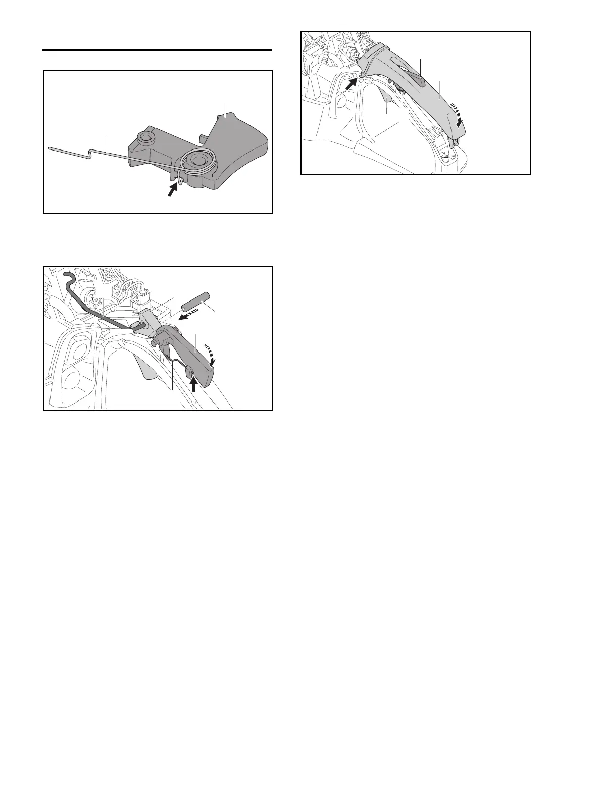
16.3 Installing Trigger Lockout, Throttle Trigger and
Throttle Linkage
N Fit torsion spring (3) on throttle trigger (4).
N Engage leg (arrow) of torsion spring (3) in throttle
trigger (4).
N Place throttle trigger (4) with torsion spring (3) in the
handle housing.
N Use a 5 mm pin punch to drive the pin (5) into the
bore in the handle housing.
N Swing torsion spring (3) to side of handle and attach
throttle linkage (2) to the throttle trigger (4).
N Depress throttle trigger (4) and place the lockout lever
(6) in the handle housing so that the torsion spring (3)
is under the lever’s pivot.
N Swing the lockout lever (6) towards the handle
housing.
N Attach torsion spring (3) to the guide (arrow) on the
lockout lever (6).
N Push the handle molding (1) into the guides (arrow) in
the handle housing as far as stop.
N Swing the handle molding (1) downwards, making
sure the lockout lever (6) and torsion spring (3) do not
pop out.
N Engage the handle molding (1) in position.
N Try to pull the throttle trigger (4) without depressing
the lockout lever (6).
N If the trigger (4) can be pulled: Remove and then re-
install the lockout lever (6) and throttle trigger (4).
Replace damaged parts.
N Install sleeve and throttle body, @ 15.5.
N Install the filter base, @ 15.3.
N Install the air filter.
N Fit the filter cover.
1
3
5
2
0000-GXX-5600-A0

 Loading...


