MS 500i 45
23.6 Removing Fuel Suction Hose Inside the Tank
N Preparations, @ 3.1.
N Remove the filter cover
N Remove the air filter.
N Remove the filter base, @ 3.1.
N Pull the fuel suction hose outside the tank (7) with
nipple (6) out of the fuel suction hose inside the tank
(5), @ 20.2.
Fuel suction hose outside the tank (7) remains on the
injection pump.
N Grip the fuel suction hose inside the tank (5) by the
flange and pull it out of the tank housing (2).
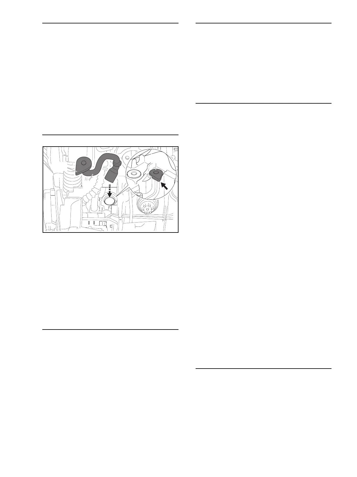
23.7 Installing Fuel Suction Hose Inside the Tank
N Push the fuel suction hose (5) into the tank housing
(2).
N Press home flange (13) as far as stop so that its
contour matches that of the guide on the tank housing
(2) (arrow).
N Push the fuel suction hose (7) with nipple (6) into the
fuel suction hose (5) as far as stop, @ 20.3.
N Install the filter base, @ 15.2.
N Install the air filter.
N Fit the filter cover.
23.8 Removing Fuel Return Hose Grommet
N Preparations, @ 3.1.
N Remove the filter cover
N Remove the air filter.
N Remove the filter base, @ 15.2.
N Pull the fuel return hose (9) with nipple (10) out of the
grommet (11), @ 20.6.
The fuel return hose (9) remains on the injection module.
N Pry the grommet (11) out of the tank housing (2).
23.9 Installing Fuel Return Hose Grommet
N Push grommet (11) into tank housing (2) as far as
stop.
N Push the fuel return hose (9) with nipple (10) into the
grommet (11) as far as stop, @ 20.7.
N Install the filter base, @ 15.3.
N Install the air filter.
N Fit the filter cover.
23.10 Removing the Tank Housing
N Preparations, @ 3.1.
N Remove the filter cover
N Remove the air filter.
N Remove the shroud.
N Remove spark plug boot and pull ignition lead out of
the guides, @ 19.3.
N Remove the filter base, @ 15.2.
N Remove the throttle body and sleeve, @ 15.4.
N Remove the controller, @ 19.7.
N Pull generator’s wiring harness out of the guides in
the tank housing and airflow housing, @ 22.2.
N Remove trigger lockout, throttle trigger and throttle
linkage, @ 16.2.
N Remove the injection pump, @ 21.2.
N Remove the handlebar, @ 9.2.
N Remove screw from AV element between tank
housing (2) and crankcase, @ 17.2.
N Pull the fuel suction hose outside the tank (7) with
nipple (6) out of the fuel suction hose inside the tank
(5).
Fuel hose (7) remains on the injection pump.
N Remove fuel hose from guide in the tank housing, @
20.4.
N Pull the fuel return hose (9) with nipple (10) out of the
grommet (11), @ 20.5.
The fuel return hose (9) remains on the injection module.
N Remove impulse hose from guide in the tank housing,
@ 20.4.
N Lift away the tank housing (2).
23.11 Installing the Tank Housing
N Place the tank housing (2) against the crankcase.
N Fit impulse hose in the guide in the tank housing, @
20.8.
N Install the fuel return hose (9) with nipple (10), @
20.7.
N Fit fuel hose in the guide in the tank housing, @ 20.5.
N Install the fuel suction hose (7) with nipple (6), @
20.3.

 Loading...


