Reference N-11
Notes
10MAY01
Technical Notes
Modeling with the T10 Tip (0.010-inch)
The T10 tip (0.010-inch) is designed for small, thin-walled, fine featured or
highly detailed parts. When used with the .007-inch slice increment, superior
surface is also achieved. The T10 tip is currently available on the FDM 2000/
3000/8000.
T10 Features
Features of the T10 tip include:
• A .01-inch inside diameter and a .03-inch
outside diameter.
• Use of a smaller nozzle outside diameter to
improve the modeling of small features.
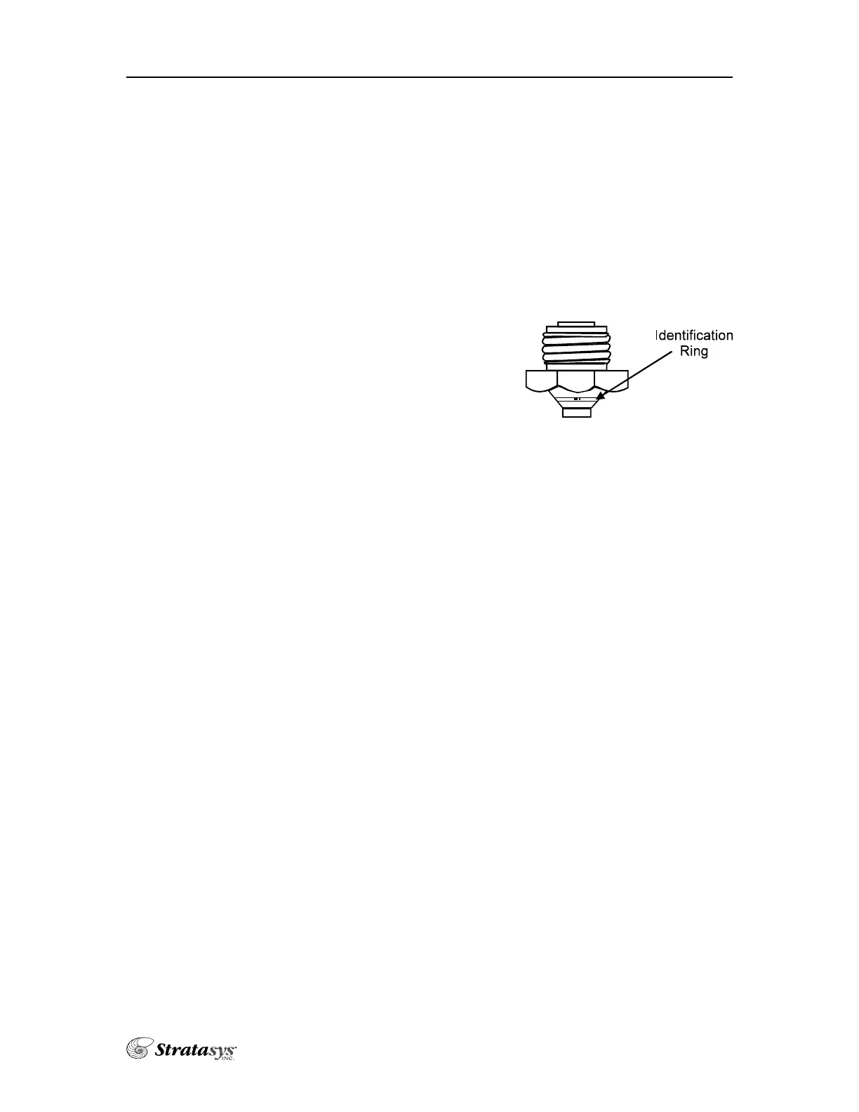
• An identification ring engraved into the tip
for easy identification.
• .007 and .010 Def files
Setup Procedures Unique to the T10 Tip
• For ABS material, set the model liquefier temperature at 290°.
• Use the T10 tip for the model side and T12 for the support side.
• Set the envelope temperature at 60°. Parts that are less than 1.5”sq. can run
with a 50° envelope.
• Use of a run speed of 1 inch per second for all curves.
• Use a contour and raster toolpath width range between .01 – .028 inches.
• Run the calibration procedure whenever you change a tip. Proper calibra-
tion is very important, particularly in the Z-axis. If necessary, refer to the
calibration procedures in the hardware section of your FDM manual.
• Purge the model side liquefier prior to running a model (let the model side
load until the “load time fault” flashes on the key pad screen).
• Run parts in the center of the foam when possible.
Single
 Loading...