1-14 1025-009-005 REV B www.stryker.com
TRANSPORTING THE STRETCHER USING THE DRIVE WHEEL (CONTINUED)
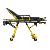
4. Grasp the drive handles at the two raised grip areas. Squeeze either of the motion release switches (A) located
under the handles to enable the movement of the drive wheel as shown in Figure 4 and in the Drive Wheel Pedal
and Drive Handle Reference label. Either or both switches will enable movement but both switches must be released
to stop movement.
5. While continuing to squeeze the switch(es), push the handles away from you or pull the handles toward you to
initiate motion in that direction. The speed of the drive wheel will increase proportionally to the amount of force
applied to the drive handles. When the desired speed is reached, the stretcher will maintain speed and direction
with no extra push force. To accelerate, push or pull the handles again until the desired speed is reached. Relax the
force to a “neutral” position to maintain speed.
6. To slow down the motion of the stretcher, push or pull the handles in the opposite direction the stretcher is currently
moving.
7. To stop motion, remove your hands from the switches
and the handles.
Note
The drive wheel does not pivot. The unit cannot be moved
directly sideways with the drive wheel engaged. With the
drive wheel pedal in the neutral position and the unit’s
brakes released, the unit can be moved in any direction
including sideways.
To transport the stretcher without using the drive wheel,
put the pedal in the neutral position and put the “On/ Drive
- Off/Manual” switch in the Off position. This allows the
stretcher to be maneuvered with the assistance of the
Big Wheel
®
but without power assistance from the ZOOM
®
drive wheel.
WARNING
Do not attempt to push the unit manually with the drive wheel engaged and the “On/Drive - Off/Manual” switch in the
On position. The unit will be difficult to push and injury could result.
CAUTION
Always unplug the power cord and rotate the “On/Drive - Off/Manual” switch to the Off position before service or
cleaning.
Return To Table of Contents
Stretcher Operation
A
STORED POSITION
Figure 4 - Drive Handles with Motion Release Switches
Figure 5 - Drive Handles - Stored Position
Drive Wheel Pedal and Drive Handle Reference Label
 Loading...