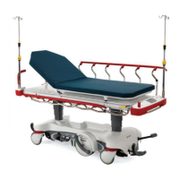
FFiigguurree 1155 –– SSiiddeerraaiill aasssseemmbbllyy rreeppllaacceemmeenntt ((XXPPSS))
4. Using a slotted screwdriver, remove the outer rail bumper.
NNoottee
• Hold on to the siderail main assembly when you remove the outer rail bumper to prevent the outer rail bumper from
falling off.
• The head end and middle siderail pivots may be loose and could fall off of the main assembly.
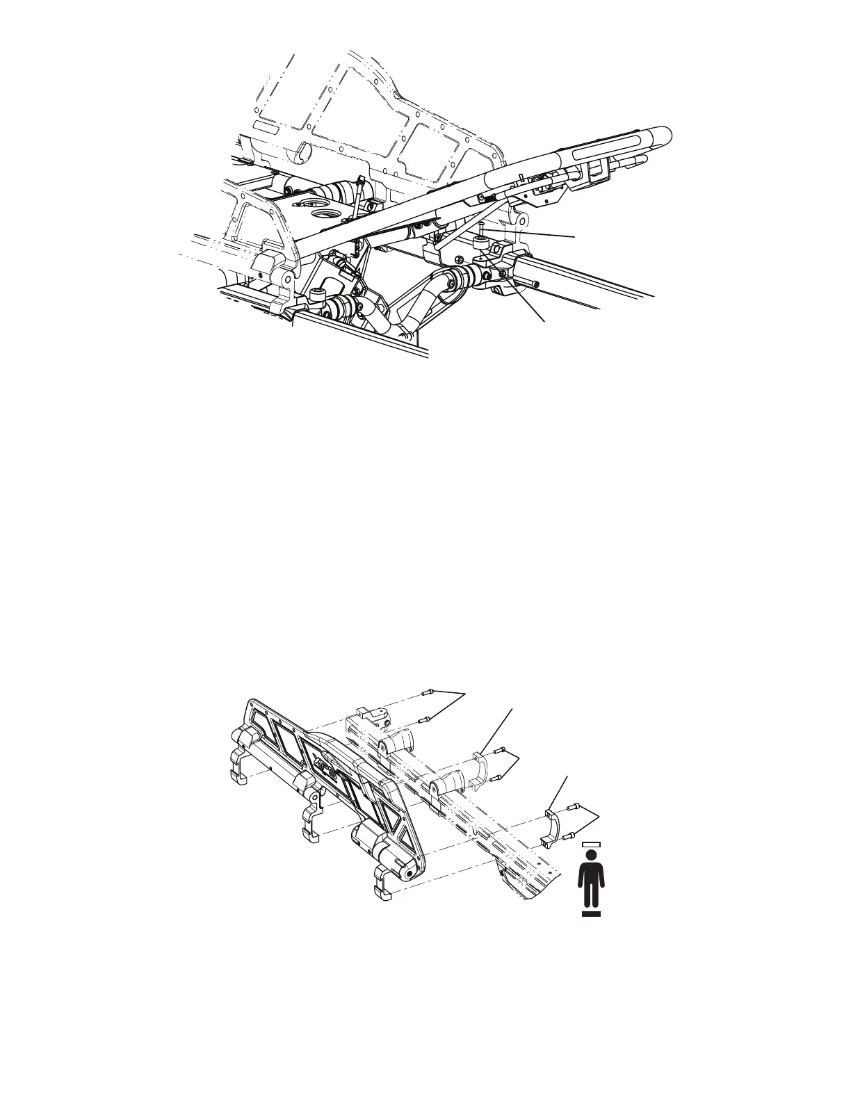
5. Using a 1/4" hex wrench, remove the socket head cap screws (C) that secure the siderail clamp (D) to the ratchet
assembly at the foot end of the main assembly (Figure 16). When you reinstall, use a torque wrench to torque both new
screws to 22 ± 3.3 ft-lb.
NNoottee -- The siderail will be loose, so do not operate or pull on the siderail.
6. Using a 3/16" hex wrench, remove the two socket head cap screws (E) that secure the middle siderail clamp (F) to the
outer rail assembly (Figure 16).
7. Using a 3/16" hex wrench, remove the two socket head cap screws (G) that secure the top and bottom of the base/litter
interface bracket to the outer rail assembly (Figure 16).
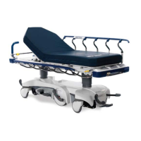
FFiigguurree 1166 –– RReemmoovvee tthhee ssiiddeerraaiill aasssseemmbbllyy
8. Reverse steps to reinstall. Use a rubber mallet to reinstall the outer rail bumper.
9. Verify proper operation before you return the product to service.
EN 22 6086-009-002 Rev AB.2