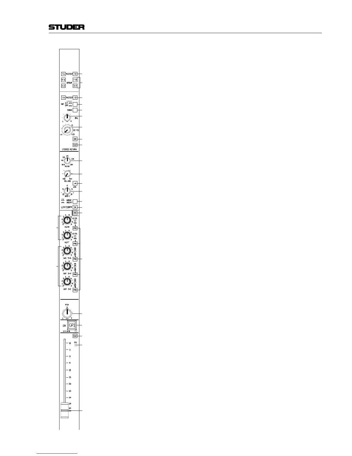
GROUP CHANNEL:
[16] INS
Electronically balanced insert point. If the INS key is pressed and illu-
minated, the signal path is routed via the INSERT SEND/RETURN con-
nectors, else the signal path is routed internally.
The signal is always available on the INSERT SEND connector, re-
gardless of the INS key.
[17] AUX 7, AUX 8
Outputs to the stereo auxiliary busses 7 and 8. The (pre- or post-fader)
group signal can be mixed to the desired AUX bus with the concentric
potentiometers. The small knobs are the level controls, while the outer
rings are used as PAN controls.
[18] AUX 1+2, AUX 3+4, AUX 5+6
Outputs to the mono auxiliary busses 1...6. The (pre- or post-fader)
group signal can be mixed to the desired AUX bus with the concentric
potentiometers; the knobs are the level controls for the odd-numbered
AUX busses (1, 3, 5), the outer rings for the even-numbered AUX
busses (2, 4, 6).
[19] PRE
If PRE is pressed, the pre-fader signal is mixed to the AUX bus instead
of the post-fader signal, and the key is illuminated.
[20] PAN
The post-fader signal is routed to the PAN potentiometer (detent in
center position). The potentiometer is used for positioning the group
signal within the stereo image of the main (MASTER) mix or the other
group pairs; the unit's own group bus pair cannot be accessed with
the group selector.