© STULZ GmbH, Hamburg DE / 06-2016 / 1000687
-
37
-
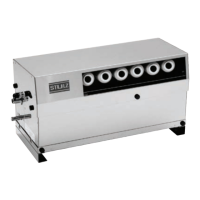
STULZ UltraSonic -System for duct humidication ENS 14 A - 18 A- Installation
CAUTION
Installation clearance.
Leave minimum clearance of longer than humidier distance between the upper edge of the ultrasonic
humidier.
●
See section "7.2. Installation clearances" on page 33.
IMPORTANT
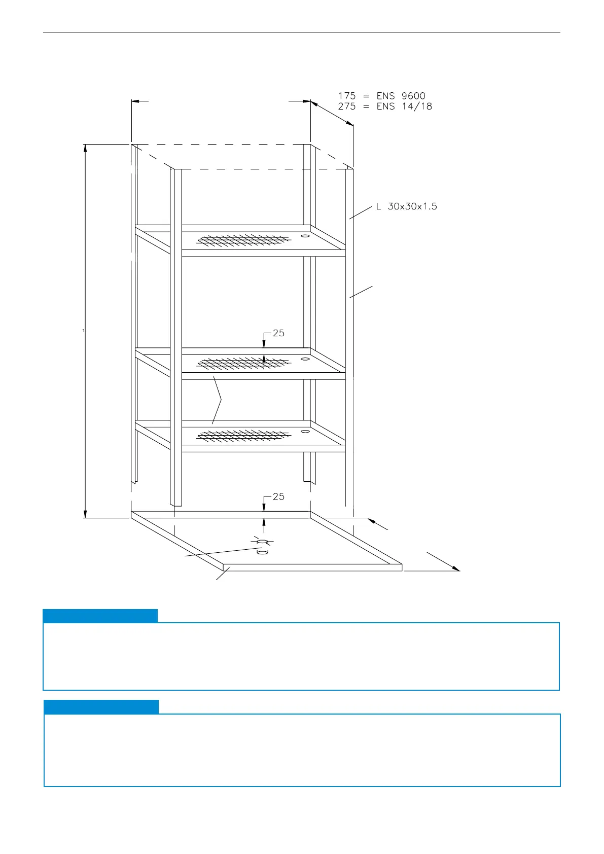
7.3.3. Example frame
A suitable frame for holding the humidiers in the air handling unit may look like the illustration below.
The frame must be produced on site.
ULTRASONIC
59
Copyright STULZ GmbH 02/1997
MONTAGE MODELLREIHE ENS
Sollen mehrere ENS-Befeuchter im Kanal oder Luftbehandlungsgerät
installiert werden, so müssen die Befeuchter über den Querschnitt
verteilt werden, um eine gleichmäßige Verteilung der Feuchtigkeit im
Luftstrom zu erzielen.
Ein entsprechendes Gestell für die Aufnahme der Befeuchter im
Luftbehandlungsgerät kann wie abgebildet aussehen.
D71t4.P65 16.04.97, 13:4759
Unit: mm
Interior dimensions of box-type
unit
(Fit frame in oor tray)
Corner bracket
Humidication dis-
tance + 200 mm
Floor tray Mat.: Stainless steel, 1.5 mm thick
Siphon must be suitable
for differential pressure
Interior height of box-type unit
Carrier plate
CAUTION
Duct dimension
The installation clearances are not mentioned for dimensioning the duct.
●
Installing the humidier in the duct can cause a higher air ow rate which will exceed the maximum
value of 3,0 m/s.
IMPORTANT