CheckPoint Pharma and CheckPoint
e
Operation and Maintenance Manual
SUEZ © 2018 57 of 112 DLM 97200-03 EN Rev. A
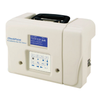
10 (gnd)
9 (+11 to +24 V)
8 (-)
7 (+)
TB2
Internal to Analyzer Local Control External to Analyzer
K1
Method 2 - Using Customer’s External Power Supply
Conduit
-
+
K1 = Custom Computer Terminal
12V - 28V
DC
Figure 16: Wiring Option for Binary Input Using External Supply
Step 4: Install the Sample Inlet and Waste Outlet
The Sensor is normally used in On-line mode to measure a flowing sample stream. The flow from the
water source should be disabled until the sample inlet tubing is completely installed and the Sensor is
ready to begin analysis. To ensure against introducing particulates into the Sensor, install the optional
in-line filter on the sample inlet, as well.
1. If you are using the standard inlet provided with the Sensor, attach it to the Sensor and tighten
the fitting with a 7/16 in open-end wrench. Tighten the fitting one-quarter turn past finger-tight. Do
not over tighten the fitting.
The accessories kit provides a 1/4" to 1/8" adapter in case you need the additional hardware to
connect to existing fluidics connections. The accessories kit also contains a 1/4" to 1/8" reducing
ferrule and hand-tight nut.
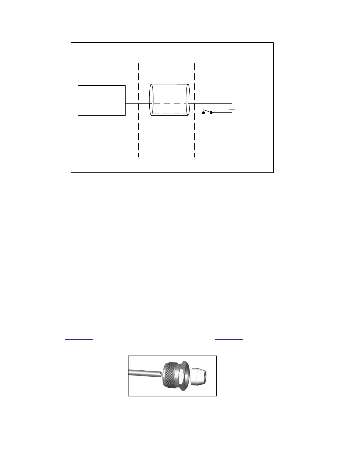
To use the reducing fittings, cut the 1/8" fitting off of the sample tube before attaching the fittings
(see Figure 17: Proper Orientation of the Reducing Ferrule and Figure 18: The Reducing Ferrule
After Installation).
Figure 17: Proper Orientation of the Reducing Ferrule