8.7 Brake Construction and Gap Inspection and Adjustment
•
The brake is spring activated (power-o type).
•
The brake lining wears after long hours of operating the brake, making it impossible for the brake to release.
Therefore, please periodically inspect the brake gap (G).
•
Adjust the gap if the gap is close to the limit during inspection.
•
In FB-1E – FB-4E, a shock absorber is inserted between the stationary core and the armature plate to reduce the
noise that results from the braking action.
•
When inspecting, be careful that the gap gauge, other measuring tool or anything else does not damage the shock
absorber or cause it to fall out.
•
There is danger that if the shock absorber is damaged or falls out, brake noise will increase and the brake will not
function properly.
Brake
Model
Motor Capacity
Standard
Braking Torque
ft - lbs (N - m)
Braking Delay Time (sec) Brake Work Capacity
Normal Braking Action
Fast Braking
Action
Allowable
E
0
(J/min)
Gap Adjust
(x 10
7
J)
Total
E1 (x 10
7
J)
HP x 4P kW x 4P
Standard
Wiring
Inverter
Wiring
[1]
FB-01A1 1/8 0.1 0.7 (1.0)
0.15 ~ 0.2 0.08 ~ 0.12 0.015 ~ 0.02
1080 2.6 6.7
FB-02A1 1/8 ~ 1/3 0.1 ~ 0.25 1.4 (2.0)
FB-05A1 1/4 ~ 1/2 0.2 ~ 0.4 2.9 (4.0) 0.1 ~ 0.15 0.03 ~ 0.07 0.01 ~ 0.015
Table 8-20: FB-01A1, FB-02A1, and FB-05A1 Standard Specications
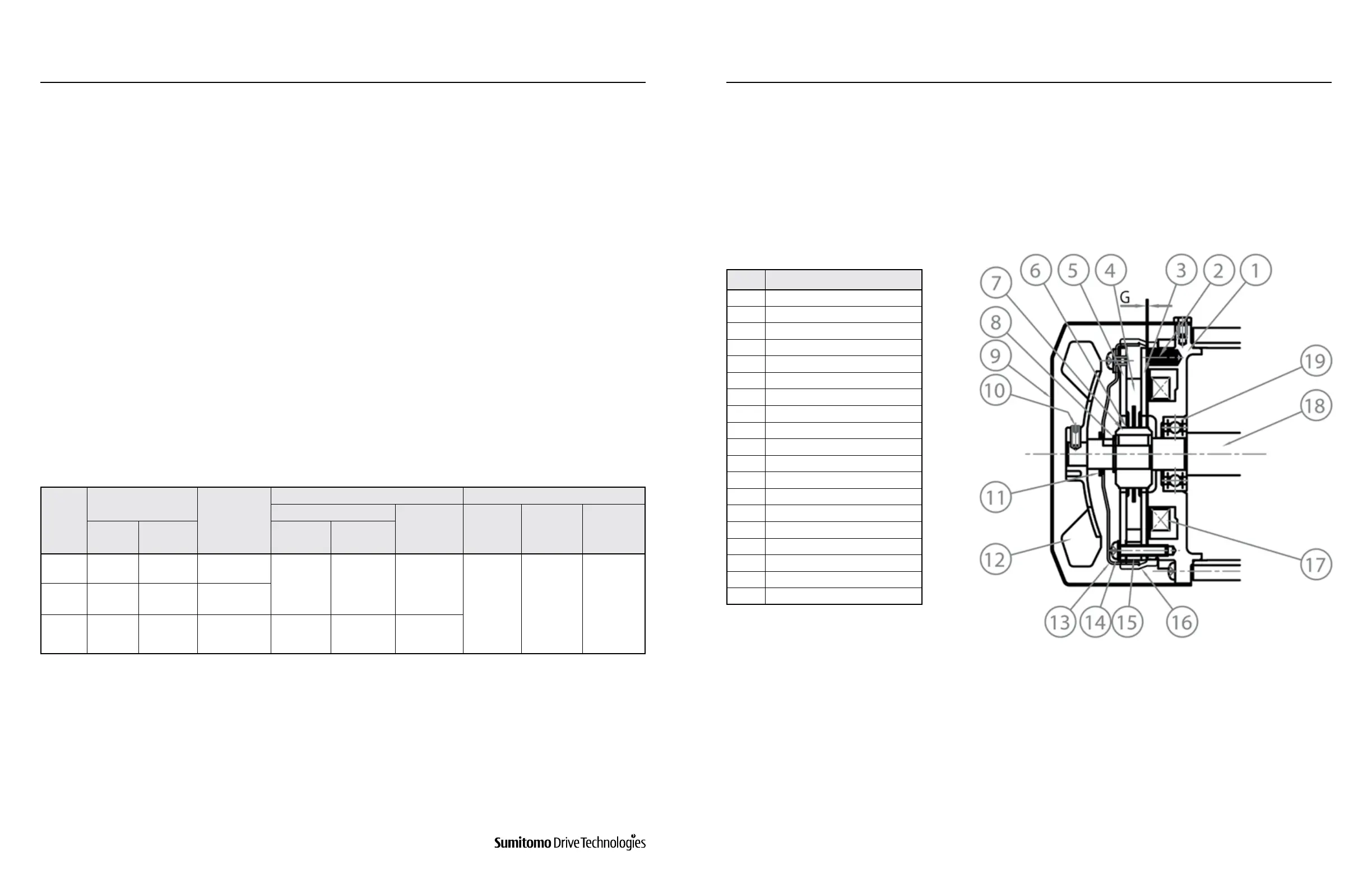
Figure 8-9: FB-01A1, FB-02A1, FB-05A1 Models
Notes:
Above table applies to standard brake specication under standard brake torque. Special brakes may perform dierently from those shown. Initial brake
torque may be lower than specied brake torque. If this is the case, under light load start and stop the motor to wear-in the braking surface. To improve
performance for positioning accuracy or lifting applications, consider using fast braking action circuit. If the brake is operated at a rate greater than the
Allowable Brake Work Capacity, E0, the brake performance may degrade or become inoperable.
* These parts are included in a complete brake kit.
[1] Also applies to wiring where brake is powered separately from the motor leads.
Brake Models FB-01A1, FB-02A1, and FB-05A1
Table 8-20 lists the standard specications for Models FB-01A1, FB-02A1, and FB-05A1.
Figure 8-9 illustrates the construction of the brake. The restraining screw (14) fastens the brake shoe (5) and spacer
(15) onto the stationary core (1). The armature plate (3) is kept form rotation by the restraining screw (14) but moves
axially by electromagnetic attraction and the tension of the pressure spring (2). The brake lining (4) is tted to the hub
(7) which is secured to the motor shaft with a key. The solenoid coil (17) is energized via a rectier provided within the
conduit box.
The brake is a (fail safe type) spring actuated type brake, which will release the brake mechanism when the solenoid
coil is energized and which will engage when the coil is de-energized.
When power is applied to the unit, the solenoid coil and the electric motor will energize, and the energized coil
attracts the armature plate (3) against the tension of the pressure spring (2). As a result, the brake lining (4) will
disengage, and the motor begins to run.
No. Part Name
1 Stationary Core*
2 Pressure Spring*
3 Armature Plate*
4 Brake Lining*
5 Brake Shoe*
6 Leaf Spring*
7 Hub*
8 C-type Retaining Ring
9 Cover
10 Set Screw (TEFC model only)
11 V-Ring
12 Fan (TEFC model only)
13 Waterproof Cover
14 Restraining Screw*
15 Spacer*
16 Waterproof Seal
17 Solenoid Coil*
18 Motor Shaft
19 Fan Side Bearing
When the power is disconnected, the solenoid coil and the electric motor is de-energized. This causes the pressure
spring (2) to actuate the armature plate (3) which in turn presses the brake lining (4) against the brake shoe (5) and
brings the motor to a quick stop.
www.SumitomoDrive.com
Cyclo® 6000 Operating and Maintenance Manual
Cyclo® 6000 Cyclo® 6000
Cyclo® 6000 Operating and Maintenance Manual
54 55
1. Standard Brakemotor Specications
2. Construction and Operating Principles
a) Construction
b) Operating Principles
8. DAILY INSPECTION AND MAINTENANCE 8. DAILY INSPECTION AND MAINTENANCE