a) At regular intervals, check that: If the brake lining is so heavily worn that gap adjustment is required, follow these steps:
b) Manual Brake Release Procedure
4. Gap Inspection
•
the unit is operating normally.
•
the brake lining is not excessively worn (or gap G is normal).
•
all the mounting screws are securely tightened.
a. Remove cover (9).
b. Remove fan (12) by loosening set screw (10) (models FB-02A1 and FB-05A1).
c. Remove waterproof seal (16).
d. Loosen restraining bolts (14), rotate the brake shoe completely counterclockwise, and re-tighten the restraining
bolts (14). After tightening the restraining bolts, measure the gap G to verify that it falls within the specication
value and the allowable limit shown in Table 8-20. (This procedure reduces the gap approximately 0.012 inch
(0.30 mm).)
e. Check for brake performance by turning system power on and o a few times.
f. Reinstall waterproof seal (16) and fan (12).
g. Replace cover (9).
a. Remove cover (9).
b. Remove fan (12) by loosening set screw (10) (models FB-02A1 and FB-05A1).
c. Remove waterproof seal (16).
d. Insert a gap gage into the space between stationary core (1) and armature plate (3). Measure the gap size at
three appropriate circumferential points.
e. The gap needs to be adjusted if the values are close to the allowable limit listed in Table 8-21.
FB-01A1, FB-02A1, and FB-05A1 brakemotors are equipped with a one touch release mechanism. To manually release
the brake with power to the unit turned o, pull the brake release lever up and out from its holder and push it forward
towards the reducer. Releasing the lever will re-engage the brake.
The brake lining will wear after the unit has been used for a long period of time. Regularly check that gap G (Figure
8-9) is at an acceptable value. If the gap G become too large, the solenoid coil may fail to pull in the armature plate
and hence cannot release the brake, resulting in the unit remaining in a continuously braked condition. Follow these
steps to inspect the brake gap:
Brake Type
Gap value G, in. (mm)
Spec. value Allowable limit
FB-01A1
0.008 - 0.014
(0.20 - 0.35)
0.02
(0.5)
FB-02A1
FB-05A1
Table 8-21: Brake Gap Size
Brake
Model
Motor Capacity
Standard
Braking Torque
ft - lbs (N - m)
Braking Delay Time (sec) Brake Work Capacity
Normal Braking Action
Fast Braking
Action
Allowable
E
0
(J/min)
Gap Adjust
(x 10
7
J)
Total
E1 (x 10
7
J)
HP x 4P kW x 4P
Standard
Wiring
Inverter
Wiring
[1]
FB-1D 1/2 ~ 3/4 0.4 ~ 0.55 5.8 (7.5)
0.2 ~ 0.3 0.1 ~ 0.15 0.01 ~ 0.02
1620 7.0 33.1
FB-2D 3/4 0.55 11 (15) 2580 6.8 29.5
FB-1E 1 0.75 5.5 (7.5) 0.25 ~ 0.45 0.15 ~ 0.25
0.01 ~ 0.03
2580 11.6 38.7
FB-1HE 1.5 1.1 8.0 (11) 0.45 ~ 0.65 0.25 ~ 0.35
3360 20.8 46.3
FB-2E 2 1.5 11 (15) 0.35 ~ 0.55 0.15 ~ 0.25
FB-3E 3 2.2 16 (22) 0.75 ~ 0.95 0.4 ~ 0.5 0.02 ~ 0.04 5720 26.3 105.3
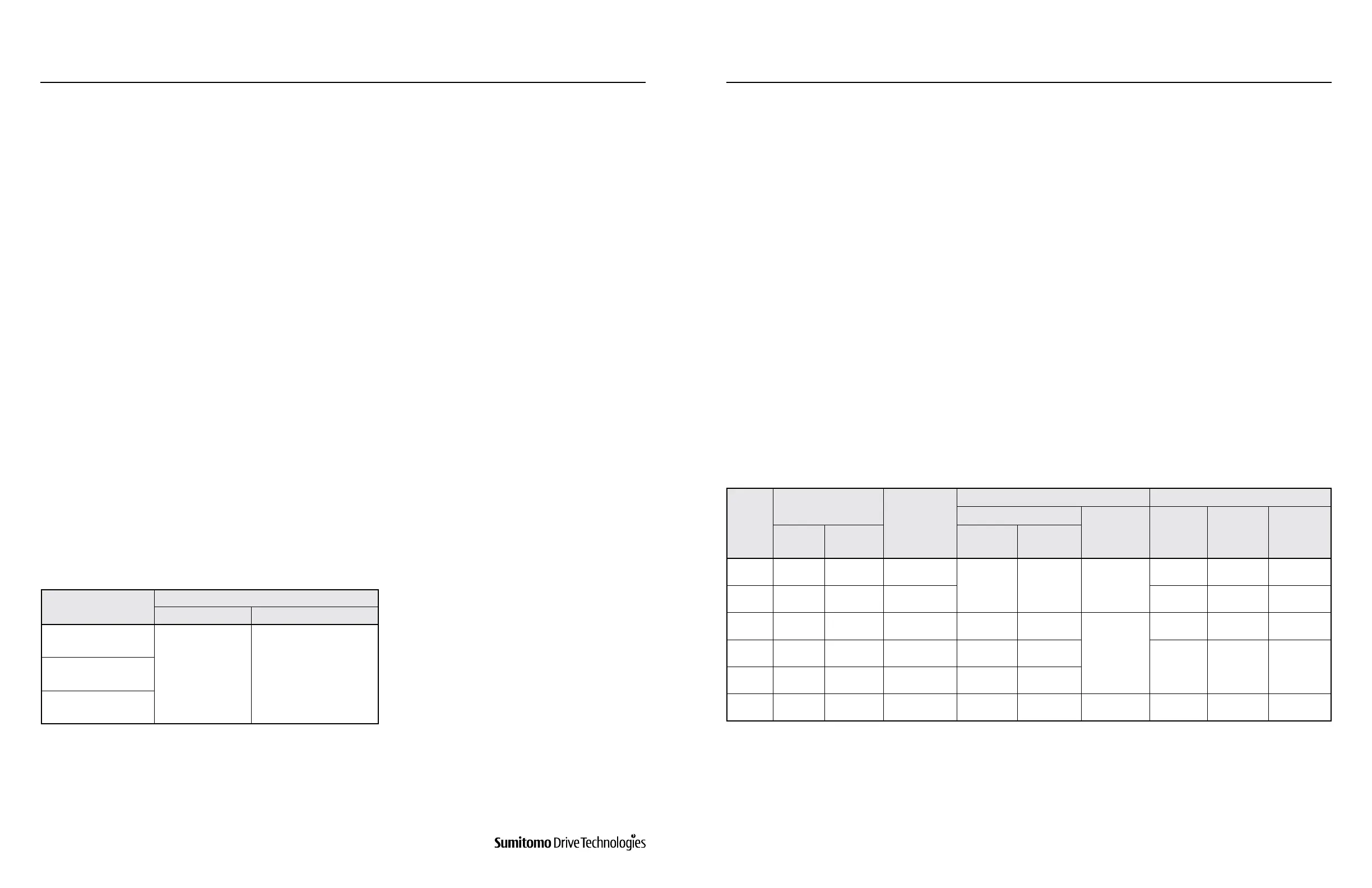
Table 8-22: FB-1D, FB-2D, FB-1E, FB-1HE, FB-2E, and FB-3E Standard Specications
Notes:
Above table applies to standard brake specication under standard brake torque. Special brakes may perform dierently from those shown. Initial brake
torque may be lower than specied brake torque. If this is the case, under light load start and stop the motor to wear-in the braking surface. To improve
performance for positioning accuracy or lifting applications, consider using fast braking action circuit. If the brake is operated at a rate greater than the
Allowable Brake Work Capacity, E0, the brake performance may degrade or become inoperable.
[1] Also applies to wiring where brake is powered separately from the motor leads.
Brake Models FB-1D, FB-2D, FB-1E, FB-1HE, FB-2E, and FB-3E
Table 8-22 lists the standard specications for Models FB-1D, FB-2D, FB-1E, FB-1HE, FB-2E, and FB-3E.
1. Standard Brakemotor Specications
www.SumitomoDrive.com
Cyclo® 6000 Operating and Maintenance Manual
Cyclo® 6000 Cyclo® 6000
Cyclo® 6000 Operating and Maintenance Manual
56 57
3. Inspection 5. Gap Adjustment
8. DAILY INSPECTION AND MAINTENANCE 8. DAILY INSPECTION AND MAINTENANCE