Brake
Model
Motor Capacity
Standard
Braking Torque
ft - lbs (N - m)
Braking Delay Time (sec) Brake Work Capacity
Normal Braking Action
Fast Braking
Action
Allowable
E
0
(J/min)
Gap Adjust
(x 10
7
J)
Total
E1 (x 10
7
J)
HP x 4P kW x 4P
Standard
Wiring
Inverter
Wiring
[1]
FB-5E 5 3.7 30 (40) 1.1 ~ 1.3 0.4 ~ 0.5
0.02 ~ 0.04
6900 57.4 382.8
FB-8E 7.5 5.5 40 (55) 1.0 ~ 1.2 0.3 ~ 0.4
FB-10E 10 7.5 59 (80) 1.8 ~ 2.0 0.6 ~ 0.7
10800 110.2 551.1
FB-15E 15 11 80 (110) 1.6 ~ 1.8 0.5 ~ 0.6
Table 8-25: FB-5E, FB-8E, FB-10E, and FB-15E Standard Specications
Notes:
Above table applies to standard brake specication under standard brake torque. Special brakes may perform dierently from those shown. Initial brake
torque may be lower than specied brake torque. If this is the case, under light load start and stop the motor to wear-in the braking surface. To improve
performance for positioning accuracy or lifting applications, consider using fast braking action circuit. If the brake is operated at a rate greater than the
Allowable Brake Work Capacity, E0, the brake performance may degrade or become inoperable.
[1] Also applies to wiring where brake is powered separately from the motor leads.
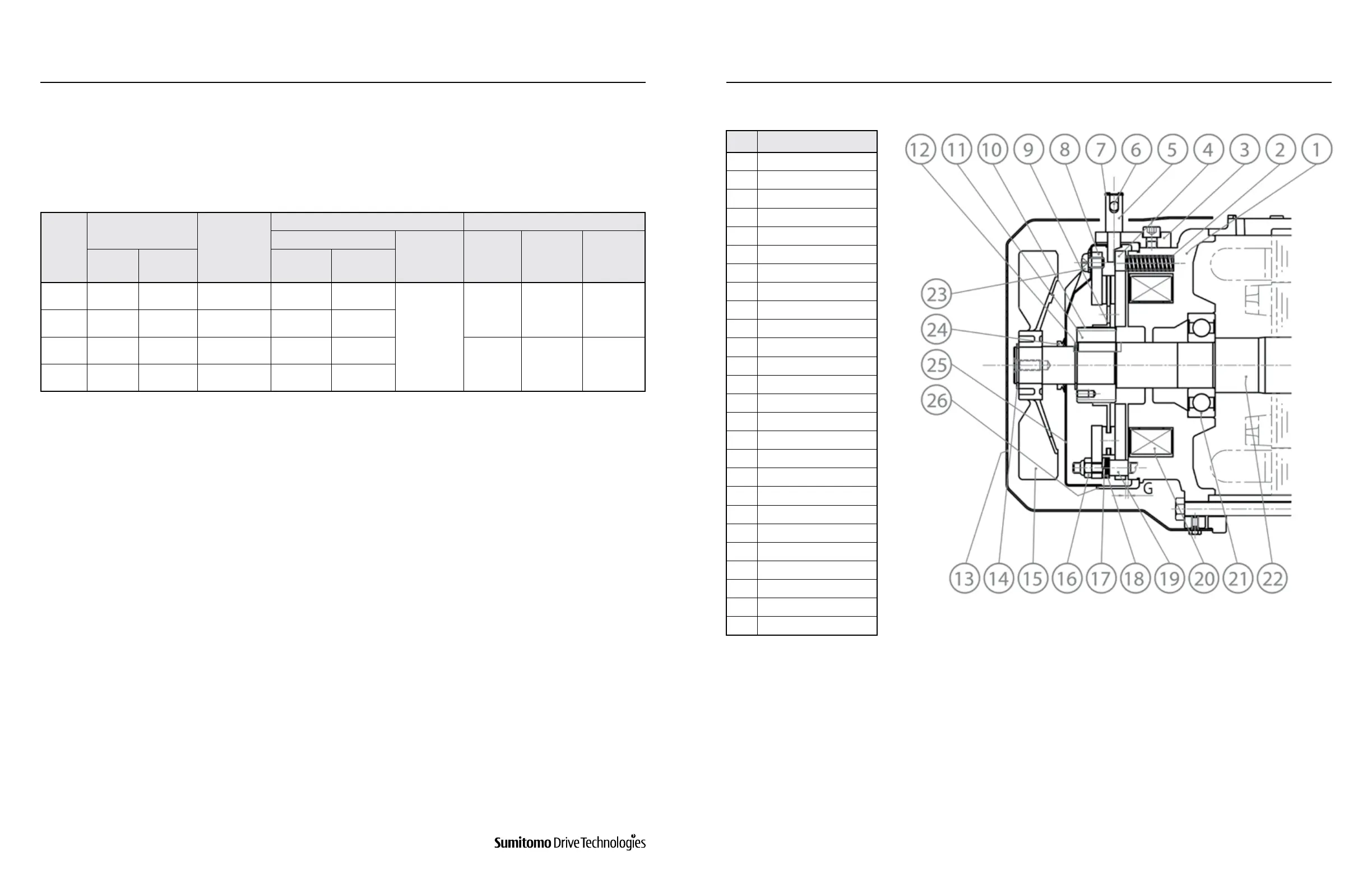
Brake Models FB-5E, FB-8E, FB-10E, and FB-15E
Table 8-25 lists the standard specications for Models FB-5E, FB-8E, FB-10E, and FB-15E.
1. Standard Brakemotor Specications
Figures 8-11 and 8-12 illustrate the construction of the brake. Among the brake parts, the stationary core (1),
solenoid coil (20), and stud bolt (19) constitute an integral subassembly unit. The stud bolt (19) keeps the armature
plate (4) from rotating, but the plate moves axially by electromagnetic attraction and the tension of the pressure
spring (2). The adjusting washer (18) and spring washer (17) hold the brake shoe (8) against the nut (16) at all times.
The brake lining (9) is t to the hub (11), which is secured to the motor shaft with a key.
2. Construction and Operating Principles
a) Construction
Figure 8-11: FB-5E and 8E Models
* These parts are included in a complete brake kit.
No. Part Name
1 Stationary Core*
2 Pressure Spring*
3 Brake Release Support
4 Armature*
5 Shifting Pin
6 Brake Release Lever
7 Retaining Clip
8 Brake Shoe*
9 Brake Lining*
10 Leaf Spring*
11 Hub*
12 C-type Retaining Ring
13 Cover
14 C-type Retaining Ring
15 Fan
16 Gap Adjusting Nut*
17 Spring Washer
18 Adjusting Washer*
19 Stud Bolt*
20 Solenoid Coil*
21 Fan Side Bearing
22 Motor Shaft
23 Attachment Screw
24 V-Ring
25 Waterproof Cover
26 Waterproof Seal
www.SumitomoDrive.com
Cyclo® 6000 Operating and Maintenance Manual
Cyclo® 6000 Cyclo® 6000
Cyclo® 6000 Operating and Maintenance Manual
62 63
8. DAILY INSPECTION AND MAINTENANCE 8. DAILY INSPECTION AND MAINTENANCE