Brake Type
Gap value G, in. (mm)
Spec. value Allowable limit Gap Adjustment Shim Thickness
FB-1D, FB-2D
0.012 - 0.016
(0.3 - 0.4)
0.024
(0.6)
0.008 - 0.01
(0.2 - 0.25)
FB-1E
0.01 - 0.014
(0.25 - 0.35)
0.024
(0.6)
0.008 - 0.01
(0.2 - 0.25)
FB-1HE, FB-2E
0.01 - 0.014
(0.25 - 0.35)
0.029
(0.75)
0.014 - 0.018
(0.35 - 0.45)
FB-3E
0.01 - 0.014
(0.25 - 0.35)
0.033
(0.85)
0.018 - 0.022
(0.45 - 0.55)
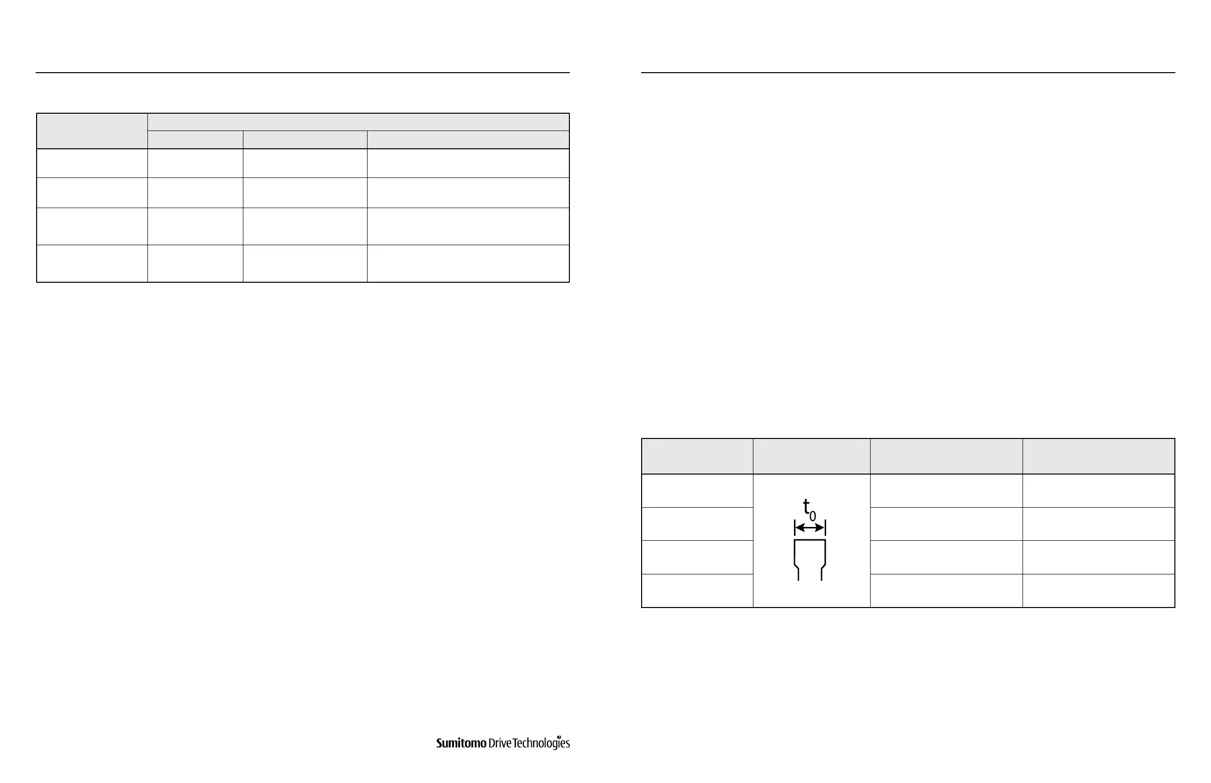
Brake Type Brake Lining Dimension
Initial Thickness
t
0
,in (mm)
Allowable Thickness
t
0
,in (mm)
FB-1D 0.276 (7.0) 0.236 (6.0)
FB-2D, FB-1E 0.347 (8.8) 0.307 (7.8)
FB-1HE, FB-2E, FB-3D 0.354 (9.0) 0.315 (8.0)
FB-3E 0.398 (10.4) 0.331 (8.4)
Table 8-23: Brake Gap Size
Table 8-24: Brake Lining Size
If the brake lining is so heavily worn that gap adjustment is required, follow these steps:
Follow these steps to replace the brake lining when its thickness has reached the allowable limit shown in Table 8-24,
or when sleeve adjustment is no longer an eective means of gap adjustment:
a. Remove shifting pins (5) and brake release lever (6).
b. Remove the cover (13). Remove fan (15) by removing retaining ring (14). Remove V-Ring (23) waterproof seal
(25) and waterproof cover (24).
c. Measure the gap size to conrm the deviation from the specication value. The minimum adjustable setting is
no less than the thickness of the Gap Adjusting Shim shown in Table 8-23.
d. Loosen the restraining bolt (16) and remove parts (16), (8), (17), and (18) as a set. Be careful not to remove only
the bolt (16) and lose the shims (17).
e. Decrease the number of shims in use according to the degree of wear (Note: Retain the removed shims for use
during the brake lining replacement procedure). Reassemble parts (16), (8), (17) and (18) as a set.
f. Once reassembled, check gap G. If the gap size is still too large, adjust the number of shims again.
g. After completing the gap adjustment, turn the system power on and o a few times to check the brake
performance.
h. Replace waterproof cover (24), waterproof seal (25), V-Ring (23), fan (15), retaining ring (14), cover (13), shifting
pins (5), and brake release lever (6).
a. Remove shifting pins (5) and brake release lever (6).
b. Remove the cover (13). Remove fan (15) by retaining ring (14). Remove V-Ring (23) waterproof seal (25) and
waterproof cover (24).
c. Loosen the restraining bolt (16) and remove parts (16), (17), (18) and (8) as a set.
d. Remove the brake lining (9), taking care to prevent the leaf spring (10) from coming o.
e. Install the new brake lining, taking care not to damage or remove the leaf spring (10). Ensure that the lining
moves smoothly along the hub (11).
f. Replace any gap adjusting shims removed and retained from previous gap adjustments. Then reinstall parts (16),
(17), (18) and (8) as a set.
g. Measure gap G. Read just if the gap is not within the specication value range.
h. Turn the system power on and o a few times to check the brake performance. If no abnormalities are detected,
replace waterproof cover (24), waterproof seal (25), V-Ring (23), fan (15), retaining ring (14), cover (13), shifting
pins (5) and brake release lever (6).
5. Gap Adjustment
6. Brake Lining Replacement
www.SumitomoDrive.com
Cyclo® 6000 Operating and Maintenance Manual
Cyclo® 6000 Cyclo® 6000
Cyclo® 6000 Operating and Maintenance Manual
60 61
8. DAILY INSPECTION AND MAINTENANCE 8. DAILY INSPECTION AND MAINTENANCE