1-8
1. Introduction|Structure
1.Introduction
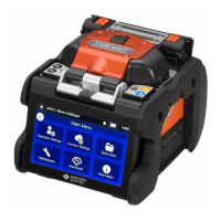
■Input/output panel
5
SD card slot
SELECT switch
DC out
ut terminal
DC input terminal
2
4 3
1
USB port
Used to download stored splice
loss data when connected to a
PC.
DC input terminal
Input power via AC adapter.
SD card slot
For splice data output.
Insert Wireless LAN SD card in
this slot when using
SumiCloud™.
DC output terminal
Used to supply DC power to a hot
jacket remover.
SELECT switch
Displays Splice/Heater program
selection screen. (▸See below)
1
2
3
4
5
We recommend you contact our service center promptly if the touchscreen does not work.
[Procedure]
1) Turn the power OFF. (if the splicer is powered on.)
2) Turn the power ON while keep holding down the SELECT switch until "Splice
Program" screen is displayed. (
▸P2-9)
3) Select splice program with HEAT keys, and then determine with SET key.
4) "Heater program" screen is displayed. (
▸P2-10) Select heater program with
HEAT keys, and then determine with SET keys.
SELECT switch feature
If the touchscreen does not work, you can select splice and heater programs by
using the SELECT switch. Follow the procedure below.
・To ensure drip-proof and dust-proof performances, close input/output panel se-
curely.
・Do not press the keys on the keypad with a sharp ob
ect (e.
. a ballpoint pen,
screwdriver, or nail) Doing so will damage the keypad.
USB port