Chapter 2 Servicing the Main Logic Board and Components 47
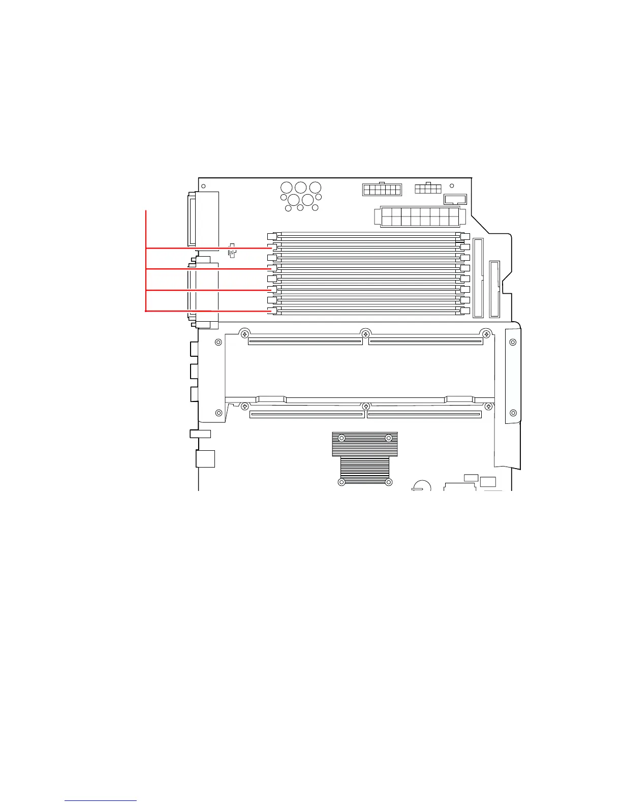
The following figure shows the location of the memory slots, with group 0
highlighted.
Before You Begin
Complete these tasks:
■ “How to Power Off the System” on page 5
■ “How to Position the System for Service” on page 14
■ “How to Remove the System Cover” on page 30
■ “How to Avoid Electrostatic Discharge” on page 35
System side
System front
Memory group 0