User Manual 5 Electrical Connection
43
During installation, press the junction box forcibly to ensure that the
pin can be inserted successfully.
Never hit the pin with a heavy object, such a hammer. Otherwise, it
will be irrecoverably.
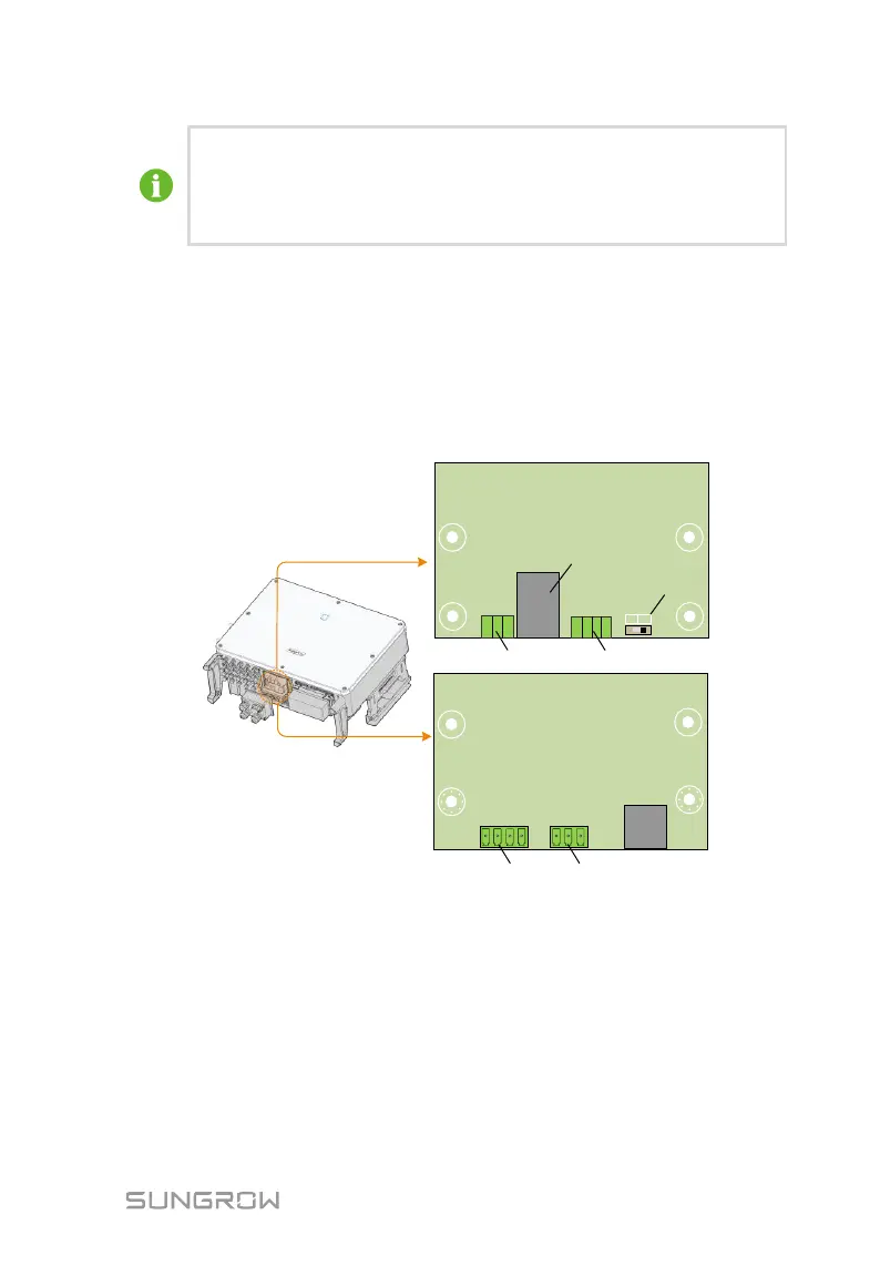
5.8 Communication Wiring Board
The communication board of the inverter includes two layers. The upper layer
communication board mainly includes RS485 communication interfaces while
the lower layer communication board mainly includes DI/DO interface and DRM
interface.
DI DI PGND
PGND
NC COM NO
DO
CON1
ON
OFF
120ohm
SW1
A1 A1 B1 B1
A2 B2
Upper layer
Lower layer
RS485
RS485
RS485-2 interface
RS485-1interface
(terminal block)
RS485-1 dip switch
Fault output dry contact
RS485-1 interface
(RJ45)
Emergency stop dry contact
5.9 RS485 Communication
5.9.1 Interface Description
As shown in the figure below, the inverter is equipped with three RS485
communication interfaces and one dip switch.