Chapter 1: Introduction
1-11
*Download the AMI status codes at http://www.ami.com/support/doc/ami_aptio_4.x_status_codes_pub.pdf
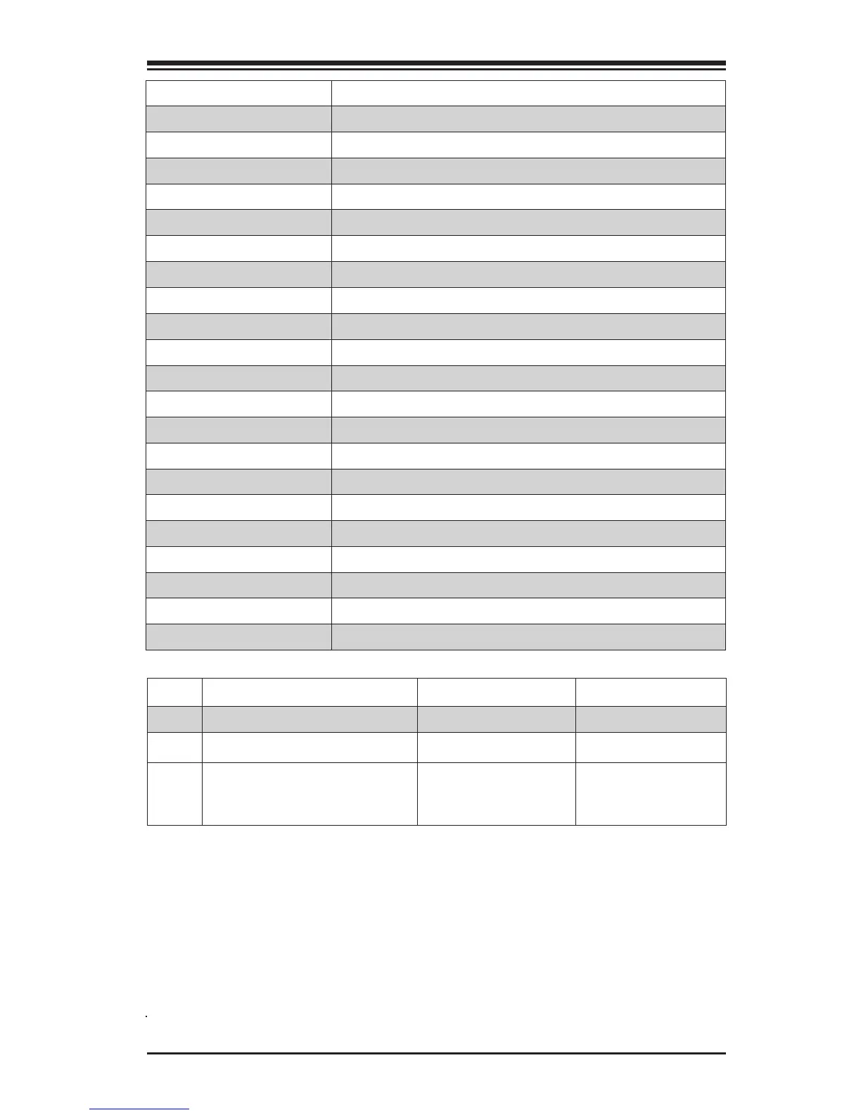
Connector Description
I/O Back Panel See Back Panel I/O Connectors, below right
Audio FP Front Panel Audio Header
Battery Onboard Battery
COM1 COM1 Port Header
Fan 1,2,3,4,5 System/CPU Fan Headers (Fan1: CPU Fan)
JD1 Speaker/buzzer (Pins 1~4: External Speaker, Pins 3~4: Buzzer)
JF1 Front Panel Control Header
JL1 Chassis Intrusion Header
JLED1 Power LED Indicator Header
JPW1 24-pin ATX Main Power Connector (Required)
JPW2 +12V 8-pin CPU power Connector (Required)
JSD1 SATA DOM (Disk On Module) Power Connector
JSPDIF_OUT Sony/Philips Digital Interface (S/PDIF) Out Header
JSTBY1 5V Standby Power Header
SP1 Internal Speaker/Buzzer
I-SATA0~5 (Intel Z170) Serial ATA (SATA 3.0) Ports 0~5 (6Gb/sec)
USB 2/3, 4/5 Front Panel Accessible USB 2.0 Headers 2/3, 4/5
USB 9/10 (3.0) Front Panel Accessible USB 3.0 Header 9/10
USB 11/12 (3.0) Front Panel Accessible USB 3.0 Header 11/12
OC FRONT PANEL Header for the Overclocking Control Panel
PCI-E M.2 CONNECTOR PCI-E M.2 Connector for memory cards, wireless adapters, etc.
LED Description Color/State Status
LED1 Onboard Standby PWR LED Green: Solid on Power On
LED2 M.2 LED Green: M.2 on board M.2 on board
LED4 Status Display Digital Readout
Download the sta-
tus codes below*

 Loading...


