2-12
Supermicro C7Z170-SQ Motherboard User’s Manual
JBR1
MH1 MH2
MH6
B1
+
J37
1
2
10
10
2
JBT1
JSTBY1
+
SP1
JD1
41
OC_FRONT_PANEL
JF1
JSD1
FAN5
FAN1
FAN4
FAN2
FAN3
S4
S8
S11
1
JPW1
LED2
A
A
LED1
JPW2
1
JL1
LED4
PCIE5
PCIE3
PCIE1
JVR1
JPUSB1
JLED1
3
JPAC1
1
3
JPL1
JPME2
JPCIE2
JPCIE6
JPCIE4
C7Z170-SQ
REV:1.01a
MAC CODE
BAR CODE
USB2/3
USB4/5
USB 6/7(3.0)
X
PWR
HDD
LED LED
NIC
1
OH/FF X
RST
PWR
ON
PCIE M.2 CONNECTOR
On: BIOS RECOVERY
O: NORMAL
JBR1
JTBT1
USB 11/12(3.0)
LAN
TPM/PORT80
INSTRUCTION
CHASSIS
JL1:
BIOS Restore
CLEAR CMOS
KB/MOUSE
USB 0/1
USB 9/10(3.0)
DIMMB2
DIMMB1
DIMMA2
DIMMA1
POWER BUTTON
HDMI
VESA DISPLAY
PORT
PCH SLOT1 PCI-E 3.0 X1 (IN X4)
CPU SLOT2 PCI-E 3.0 X4 (IN X16)
PCH SLOT3 PCI-E 3.0 X4
CPU SLOT4 PCI-E 3.0 X8 (IN X16)
PCH SLOT5 PCI-E 3.0 X1 (IN X4)
CPU SLOT6 PCI-E 3.0 X16
5V STBY POWER
2-3 DISABLE
JPUSB1:USB0/1 WAKE UP
1-2 ENABLE
JSTBY1:
JWD1:
JSD1:
2-3:DISABLE
1-2:ENABLE
JPL1:LAN
2-3:NMI
1-2:RST
WATCH DOG
CPU
2-3:ME MANUFACTURING MODE
CPU FAN
1-2:NORMAL
JPME2:
SATA DOM PWR
JTPM1:
JLED1:
3 PIN POWER LED
AUDIO FP
JBT1
CMOS CLEAR
PWR LED:PIN 1-3
JD1:
SPEAKER:PIN 4-7
JI2C1/JI2C2
ON :ENABLE
OFF:DISABLE
HD AUDIO
JF1
ALWAYS POPULATE RED SOCKET FIRST
UNB NON-ECC DDR4 DIMM REQUIRED
COM1
2-3:DISABLE
1-2:ENABLE
JPAC1:AUDIO
JL2
JI2C2
JI2C1
JBR1
OC_FRONT_PANEL
I-SATA2
I-SATA3
I-SATA1
I-SATA5
I-SATA0
I-SATA4
DVI-D
USB 8 (3.1)
Type C
JSPDIF_OUT
S/PDIF OUT
BIOS
JWD1
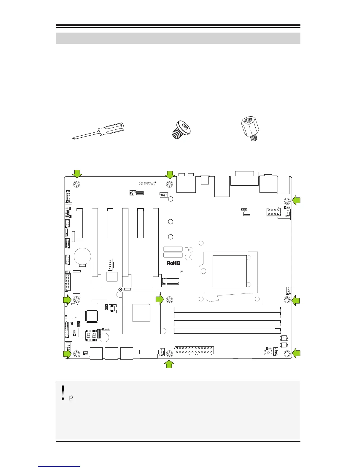
Location of Mounting Holes
Attention! 1) To avoid damaging the motherboard and its com-
ponents, please do not use a force greater than 8 lb/inch on each
mounting screw during motherboard installation. 2) Some compo-
nents are very close to the mounting holes. Please take precautionary
measures to avoid damaging these components when installing the
motherboard to the chassis.
2-5 Motherboard Installation
All motherboards have standard mounting holes to t different types of
chassis. Make sure that the locations of all the mounting holes for both
motherboard and chassis match. Although a chassis may have both plas-
tic and metal mounting fasteners, metal ones are highly recommended
because they ground the motherboard to the chassis. Make sure that the
metal standoffs click in or are screwed in tightly. Then use a screwdriver
to secure the motherboard onto the motherboard tray.
Philips Screwdriver
(1)
Standoffs (9)
Only if Needed
Philips Screws (9)
Tools Needed

 Loading...


