Chapter 2: Installation
2-15
JBR1
MH1 MH2
MH6
B1
+
J37
1
2
10
10
2
JBT1
JSTBY1
+
SP1
JD1
41
OC_FRONT_PANEL
JF1
JSD1
FAN5
FAN1
FAN4
FAN2
FAN3
S4
S8
S11
1
JPW1
LED2
A
A
LED1
JPW2
1
JL1
LED4
PCIE5
PCIE3
PCIE1
JVR1
JPUSB1
JLED1
3
JPAC1
1
3
JPL1
JPME2
JPCIE2
JPCIE6
JPCIE4
C7Z170-SQ
REV:1.01a
MAC CODE
BAR CODE
USB2/3
USB4/5
USB 6/7(3.0)
X
PWR
HDD
LED LED
NIC
1
OH/FF X
RST
PWR
ON
PCIE M.2 CONNECTOR
On: BIOS RECOVERY
O: NORMAL
JBR1
JTBT1
USB 11/12(3.0)
LAN
TPM/PORT80
INSTRUCTION
CHASSIS
JL1:
BIOS Restore
CLEAR CMOS
KB/MOUSE
USB 0/1
USB 9/10(3.0)
DIMMB2
DIMMB1
DIMMA2
DIMMA1
POWER BUTTON
HDMI
VESA DISPLAY
PORT
PCH SLOT1 PCI-E 3.0 X1 (IN X4)
CPU SLOT2 PCI-E 3.0 X4 (IN X16)
PCH SLOT3 PCI-E 3.0 X4
CPU SLOT4 PCI-E 3.0 X8 (IN X16)
PCH SLOT5 PCI-E 3.0 X1 (IN X4)
CPU SLOT6 PCI-E 3.0 X16
5V STBY POWER
2-3 DISABLE
JPUSB1:USB0/1 WAKE UP
1-2 ENABLE
JSTBY1:
JWD1:
JSD1:
2-3:DISABLE
1-2:ENABLE
JPL1:LAN
2-3:NMI
1-2:RST
WATCH DOG
CPU
2-3:ME MANUFACTURING MODE
CPU FAN
1-2:NORMAL
JPME2:
SATA DOM PWR
JTPM1:
JLED1:
3 PIN POWER LED
AUDIO FP
JBT1
CMOS CLEAR
PWR LED:PIN 1-3
JD1:
SPEAKER:PIN 4-7
JI2C1/JI2C2
ON :ENABLE
OFF:DISABLE
HD AUDIO
JF1
ALWAYS POPULATE RED SOCKET FIRST
UNB NON-ECC DDR4 DIMM REQUIRED
COM1
2-3:DISABLE
1-2:ENABLE
JPAC1:AUDIO
JL2
JI2C2
JI2C1
JBR1
OC_FRONT_PANEL
I-SATA2
I-SATA3
I-SATA1
I-SATA5
I-SATA0
I-SATA4
DVI-D
USB 8 (3.1)
Type C
JSPDIF_OUT
S/PDIF OUT
BIOS
JWD1
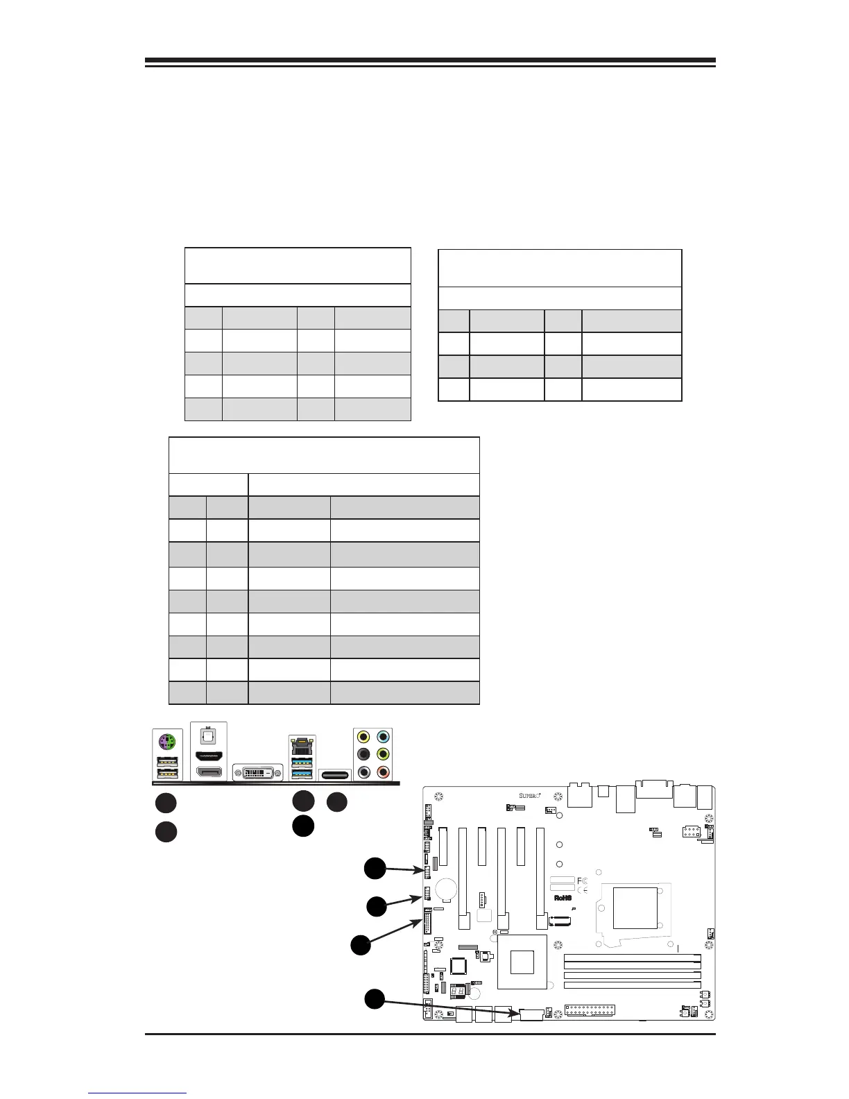
A. Backpanel USB 2.0 #0
B. Backpanel USB 2.0 #1
C. Backpanel USB 3.0 #6
D. Backpanel USB 3.0 #7
E. Backpanel USB 3.1 #8
F. USB 2.0 Header #2/3
G. USB 2.0 Header #4/5
H. USB 3.0 Header #9/10
I. USB 3.0 Header #11/12
Universal Serial Bus (USB)
Two Universal Serial Bus 2.0 ports (#0/1), two USB 3.0 ports (#6/7)
and one USB 3.1 'type C' port (#8) are located on the I/O back panel.
In addition, two USB 3.0 headers (four ports: #9/10, #11/12), and one
USB 2.0 header (two ports: #4/5) are also located on the motherboard
to provide front chassis access using USB cables (not included). See the
tables below for pin denitions.
Back Panel USB (2.0) #0/1, USB (3.0) #6/7
Pin Denitions
Pin# Denition Pin# Denition
1 +5V 5 +5V
2 USB_PN1 6 USB_PN0
3 USB_PP1 7 USB_PP0
4 Ground 8 Ground
Front Panel USB (2.0) Header #4/5
Pin Denitions
Pin # Denition Pin # Denition
1 +5V 2 +5V
3 USB_PN2 4 USB_PN3
5 USB_PP2 6 USB_PP3
7 Ground 8 Ground
9 Key 10 Ground
A
Front Panel USB (3.0) Header #9/10, #11/12
Pin Denitions
Pin# Pin# Signal Name Description
1 10 VBUS Power
2 11 D- USB 2.0 Differential Pair
3 12 D+
4 13 Ground Ground of PWR Return
5 14 StdA_SSRX- SuperSpeed Receiver
6 15 StdA_SSRX+ Differential Pair
7 16 GND_DRAIN Ground for Signal Return
8 17 StdA_SSTX- SuperSpeed Transmitter
9 18 StdA_SSTX+ Differential Pair
C
E
B

 Loading...


