Chapter 2: Installation
2-33
JBR1
MH1 MH2
MH6
B1
+
J37
1
2
10
10
2
JBT1
JSTBY1
+
SP1
JD1
41
OC_FRONT_PANEL
JF1
JSD1
FAN5
FAN1
FAN4
FAN2
FAN3
S4
S8
S11
1
JPW1
LED2
A
A
LED1
JPW2
1
JL1
LED4
PCIE5
PCIE3
PCIE1
JVR1
JPUSB1
JLED1
3
JPAC1
1
3
JPL1
JPME2
JPCIE2
JPCIE6
JPCIE4
C7Z170-SQ
REV:1.01a
MAC CODE
BAR CODE
USB2/3
USB4/5
USB 6/7(3.0)
X
PWR
HDD
LED LED
NIC
1
OH/FF X
RST
PWR
ON
PCIE M.2 CONNECTOR
On: BIOS RECOVERY
O: NORMAL
JBR1
JTBT1
USB 11/12(3.0)
LAN
TPM/PORT80
INSTRUCTION
CHASSIS
JL1:
BIOS Restore
CLEAR CMOS
KB/MOUSE
USB 0/1
USB 9/10(3.0)
DIMMB2
DIMMB1
DIMMA2
DIMMA1
POWER BUTTON
HDMI
VESA DISPLAY
PORT
PCH SLOT1 PCI-E 3.0 X1 (IN X4)
CPU SLOT2 PCI-E 3.0 X4 (IN X16)
PCH SLOT3 PCI-E 3.0 X4
CPU SLOT4 PCI-E 3.0 X8 (IN X16)
PCH SLOT5 PCI-E 3.0 X1 (IN X4)
CPU SLOT6 PCI-E 3.0 X16
5V STBY POWER
2-3 DISABLE
JPUSB1:USB0/1 WAKE UP
1-2 ENABLE
JSTBY1:
JWD1:
JSD1:
2-3:DISABLE
1-2:ENABLE
JPL1:LAN
2-3:NMI
1-2:RST
WATCH DOG
CPU
2-3:ME MANUFACTURING MODE
CPU FAN
1-2:NORMAL
JPME2:
SATA DOM PWR
JTPM1:
JLED1:
3 PIN POWER LED
AUDIO FP
JBT1
CMOS CLEAR
PWR LED:PIN 1-3
JD1:
SPEAKER:PIN 4-7
JI2C1/JI2C2
ON :ENABLE
OFF:DISABLE
HD AUDIO
JF1
ALWAYS POPULATE RED SOCKET FIRST
UNB NON-ECC DDR4 DIMM REQUIRED
COM1
2-3:DISABLE
1-2:ENABLE
JPAC1:AUDIO
JL2
JI2C2
JI2C1
JBR1
OC_FRONT_PANEL
I-SATA2
I-SATA3
I-SATA1
I-SATA5
I-SATA0
I-SATA4
DVI-D
USB 8 (3.1)
Type C
JSPDIF_OUT
S/PDIF OUT
BIOS
JWD1
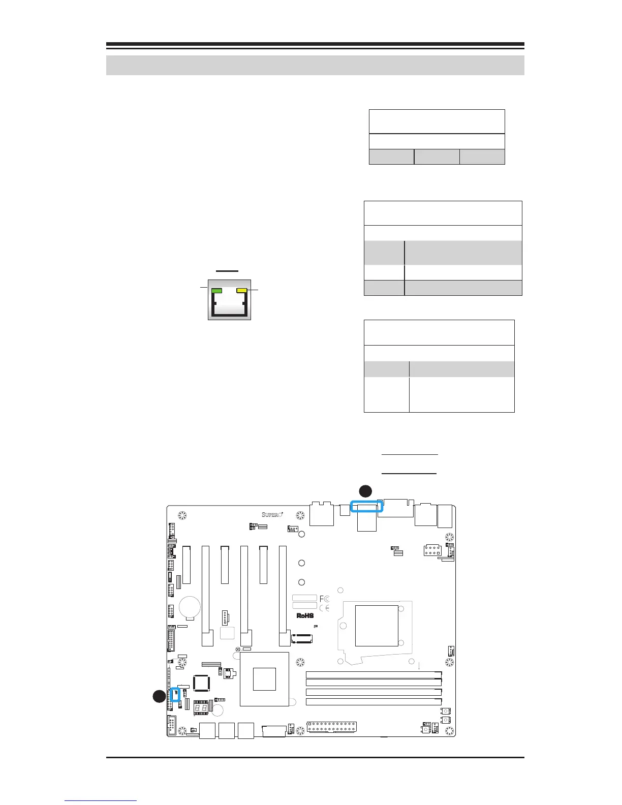
A. LAN LEDs
B. PWR LED
A
B
LAN LEDs
One LAN port is located on the I/O
backpanel of the motherboard. This
Ethernet LAN port has two LEDs (Light
Emitting Diode). The yellow LED indi-
cates activity, while the Link LED may
be green, amber, or off to indicate
the speed of the connections. See the
tables at right for more information.
2-9 Onboard Indicators
LAN
Activity LED
Link LED
Onboard PWR LED Indicator
LED Status
Status Denition
Off System Off
On System on, or
System off and PWR
Cable Connected
Onboard Power LED (LED1)
An Onboard Power LED is located at
LED1 on the motherboard. When LED1
is on, the AC power cable is connected.
Make sure to disconnect the power cable
before removing or installing any compo-
nent. See the layout below for the LED
location.
GLAN Link Indicator
LED Settings
LED Color Denition
Off No Connection/10 Mbps/100
Mbps
Amber 1 Gbps
Green 10 Gbps.
GLAN Activity Indicator
LED Settings
Color Status Denition
Yellow Flashing Active

 Loading...


