2-14
Supermicro X11SAE/X11SAE-F Motherboard User’s Manual
JBR1
JF1
JPW2
JPW1
SP1
B3
JD1
JBT1
JTBT1
JPI2C1
JSD1
JTPM1
JL1
JHD_AC1
JSTBY1
COM1
COM2
I-SATA7
I-SATA6
I-SATA5
I-SATA3
I-SATA1
I-SATA4
I-SATA2
I-SATA0
I-SGPIO2
I-SGPIO1
J23
XDP1
LEDM1
LED4
LED1
LED3
FAN5
FAN4
FAN2
FAN1
FAN3
JI2C1
JI2C2
JPAC1
JPL2
JPG1
JPB1
JPL1
JVR1
JLED1
JWD1
JPME2
MH10
MH12
MH11
1
1
1
1
1
1
1
1
1
1
1
1
1
X11SAE
REV: 1.01
MAC CODE
BAR CODE
DESIGNED IN USA
BIOS
LICENSE
BIOS RESTORE
UID
DVI/VGA
USB14/15
(3.1)
HDMI/DP
LAN1
USB8/9(3.0)
USB0/1
LAN2
SLOT2 PCI 33MHz
SLOT1 PCI 33MHz
CPU SLOT4 PCI-E 3.0 X8 (IN X16)
PCI-E 3.0 X1
PCI-E 3.0 X1PCH SLOT3
PCI-E 3.0 X16
PCH SLOT5
CPU SLOT6
PCH SLOT7 PCI-E 3.0 X1
USB6/7
USB4/5
USB2/3
USB12/13(3.0)
USB10/11(3.0)
M.2 PCI-E 3.0 X4
SLOT1 PCI 33MHz
AUDIO FP
DIMMA2
DIMMA1
DIMMB1
DIMMB2
HD AUDIO
ALWAYS POPULATE BLUE SOCKET FIRST
UNB ECC/NON-ECC DDR4 DIMM REQUIRED
CPU
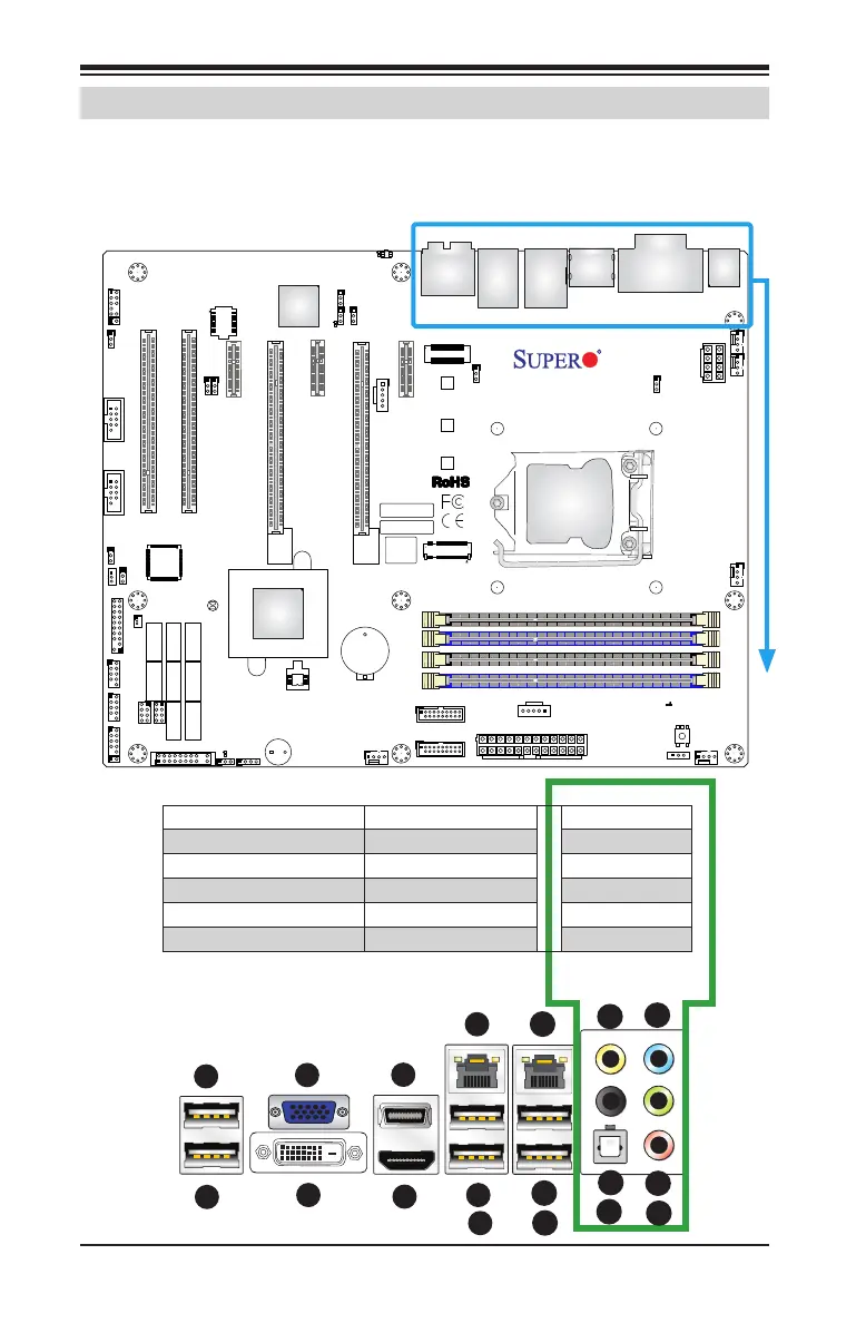
2-6 Connectors/IO Ports
The I/O ports are color coded in conformance with the industry standards.
See the gure below for the colors and locations of the various I/O ports.
Back I/O Panel
HD Audio
1. USB 3.1 Port 14 7. LAN Port 1 13. SPDIF Out
2. USB 3.1 Port 15 8. USB 3.0 Port 8 14. Surround Out
3. VGA Port 9. USB 3.0 Port 9 15. Center/LFE Out
4. DVI Port 10. LAN Port 2 16. Mic In
5. DisplayPort 11. USB 2.0 Port 0 17. Line Out
6. HDMI Port 12. USB 2.0 Port 1 18. Line In
1
9
8
7
6
5
4
3
2
10
13
12
11
1
14
1
15
1
17
1
16
1
18