1-4
X9DRW-3LN4F+/3TF+ Motherboard User’s Manual
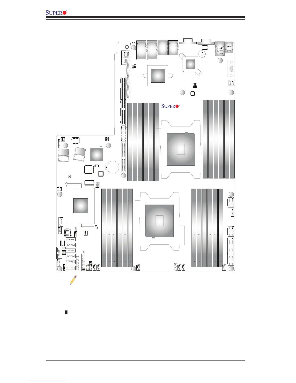
Notes:
•See Chapter 3 for detailed information on jumpers, I/O ports and JF1 front
panel connections.
•" " indicates the location of "Pin 1".
•Jumpers/LED Indicators not indicated are for testing only. The components that
are not documented are reserved for internal testing only.
•Use only the correct type of onboard CMOS battery as specied by the manufac-
turer. Do not install the onboard battery upside down to avoid possible explosion.
X9DRW-3LN4F+/3TF+ Quick Reference
JSTBY1
JRK1
JIPMB1
JPI2C1
JPW3
JPW2
JPW1
JF1
T-SGPIO1
JF2
Buzzer
JWD1
JPL2
JWP1
JBR1
JPME1
JPB1
JPL1
JPME2
JPG1
LE1
LE2
JBT1
JPP0
JPP1
JTPM1
JOH1
JL1
JP7
JP6
JI2C1
JI2C2
JBAT1
SP1
PWR_I2C
CPU1
CPU2
P2-DIMMH3
P2-DIMMH2
P2-DIMMH1
P2-DIMMG2
P2-DIMMG1
IPMI_LAN
USB0/1