Sutron Corporation Satlink Operations & Maintenance Manual, Rev 8.04.2 11/3/2016 pg. 21
4.5. Connecting the GPS Antenna
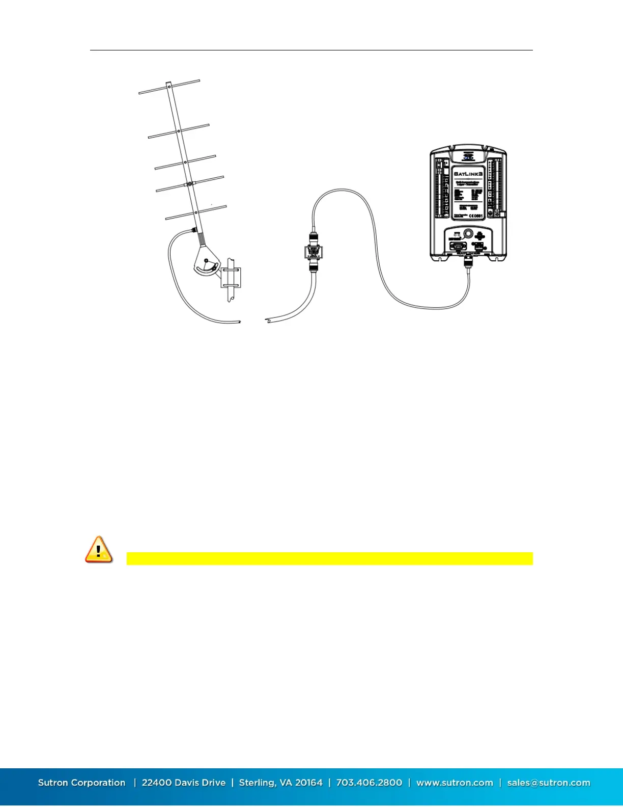
The GPS antenna connection is at the top of the SL3-1. On SL3-SDI-1, the SMA connector is to
the right of the power connection. Sutron provides a GPS antenna with each Satlink. Satlink has
special circuitry to detect whether the GPS antenna is connected.
Take care to setup the GPS antenna such that it has a clear view of the sky. A site with a strong
GPS signal will reduce overall power consumption of the station.
The GPS antenna is normally mounted outdoors. Occasionally, you may mount the GPS antenna
indoors if the GPS signal penetrates the structure or enclosure where it is located.
The GPS antenna should be installed in a way to reduce the buildup of snow that might affect its
operation.
Only approved GPS antennae should be connected to Satlink.
Satlink requires a well positioned GPS antenna in order to operate correctly.
4.6. Connecting the Power Supply
The Power/Battery connection for the SL3-1 is at the top left of the unit. A two position
removable plug is provided for the connection. SL3 operates off 9-20VDC and can use up to 4
amps. Because of the high amperage requirements, an AWG 18 wire should be used.
Note: Even though SL3 will operate below 12V some sensors will not operate when the power
supply is below 12V.


 To Next Page