Sutron Corporation Satlink Operations & Maintenance Manual, Rev 8.04.2 11/3/2016 pg. 25
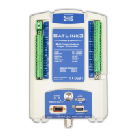
The pulse output sensors connect to the DIN #1 or DIN #2 inputs. DIN #1 supports sensors with a
low level AC output (100 mVp-p) or high level output while DIN#2 supports only sensors with a
high level output (switch closure, 0-3VDC, or 0-5VDC).
The frequency measurement circuitry can measure frequencies from 3Hz to 10KHz with an
accuracy of 0.01%. The system takes 0.75 seconds to make the measurement.
The key settings for frequency sensors are:
Measurement Type: Digital
Digital type: Frequency 1 or Frequency 2
Note: Use Frequency 1 for sensors with a low level AC output voltage (such as an
RMYoung) and specify (AC Low Level). Frequency 2 is always expecting a DC high level
signal.
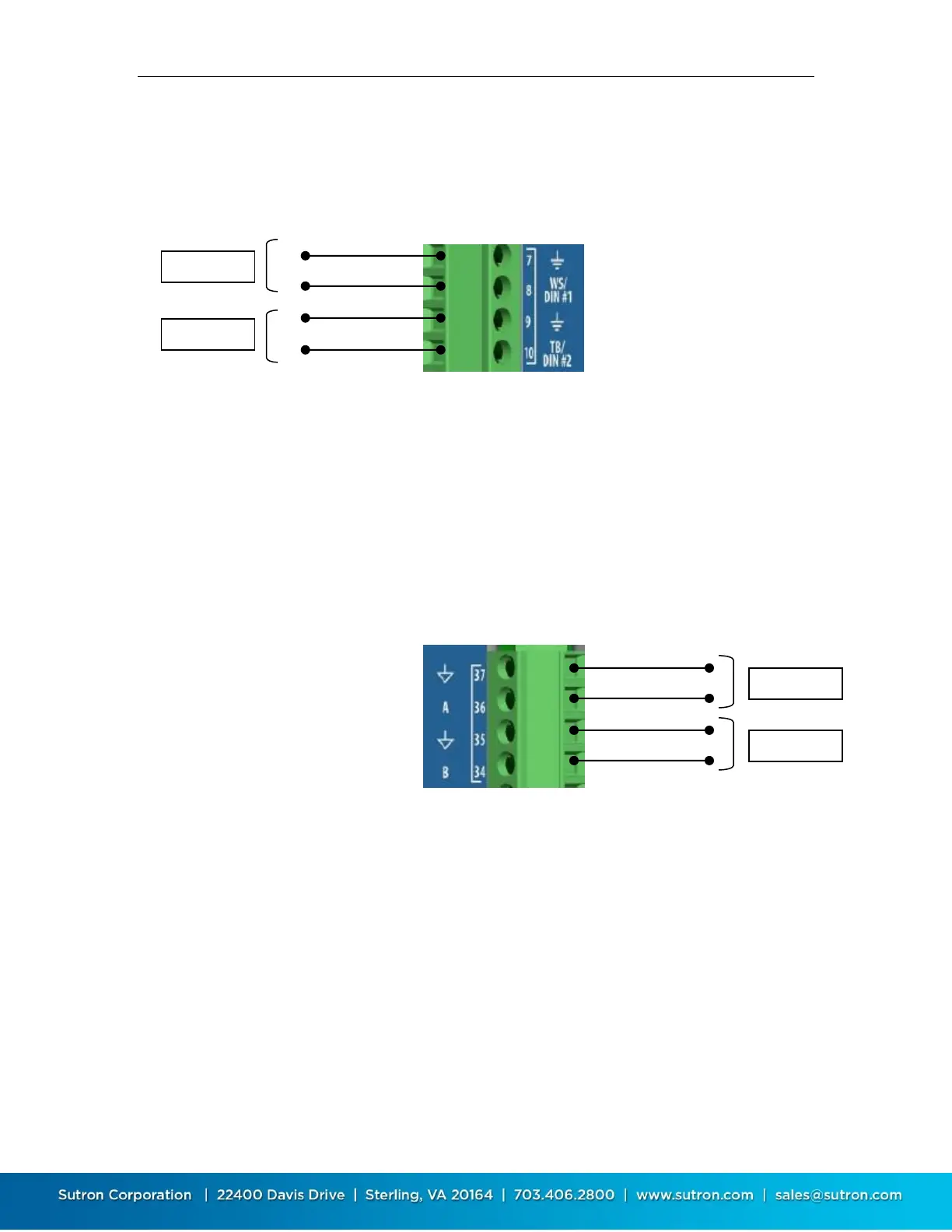
4.12. Connecting 0-5V Analog Sensors
SL3-1 supports up to two sensors with an output voltage up to 5 VDC. The sensor must be
connected to the signal ground and may be powered from VREF, PROT+12V, SWD+12V. These
inputs are compatible with sensors thermistors, potentiometers, strain gauges, etc.
The key settings for 0-5V analog sensors are:
Measurement Type: Analog
Analog Type: 0-5V A or B.
4.13. Connecting 4-20ma Analog Sensors
SL3-1 supports up to three sensors with a 4-20mA output. One sensor can connect directly to
the 4-20mA input (terminal 23) as shown below. The other sensors can connect to A or B (0-5V)
analog channels with an external load resistor. The sensor/loop must be powered from
PROT+12V, SWD+12V, main power, or other source with common ground to SL3.