Power Unit Mechanical: 1D-13
d) Remove the intake manifold (with fuel vapor
separator).
e) Remove the fuel vapor separator from intake
manifold.
Refer to “Fuel Vapor Separator Removal and
Installation” in Section 1G (Page 1G-17).
Installation
Installation is reverse order of removal with special
attention to the following steps.
Do not reuse gaskets, always replace with
new one.
• Install the fuel vapor separator to intake manifold.
Refer to “Fuel Vapor Separator Removal and
Installation” in Section 1G (Page 1G-17).
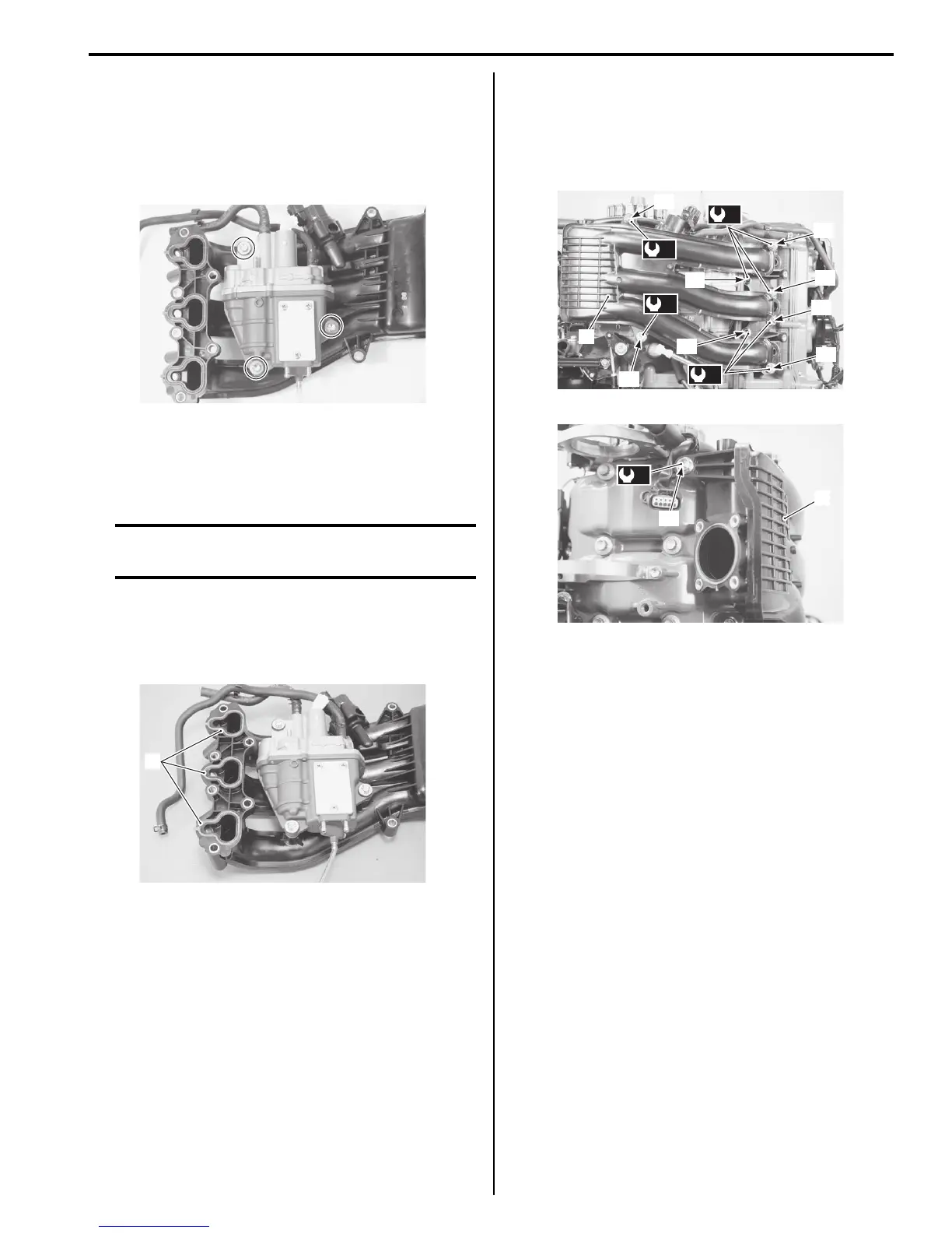
• Clean mating surface and install the seal ring (1).
• Install the intake manifold assembly (2), then tighten
bolts and nuts securely.
Tightening torque
Intake manifold bolt / nut (a): 23 N·m (2.3 kgf-m,
16.5 lbf-ft)
• Install fuel injectors and fuel delivery pipe.
Refer to “Fuel Injector Removal and Installation” in
Section 1G (Page 1G-24).
• Install the throttle body.
Refer to “Throttle Body Removal and Installation”
(Page 1D-10).
• Perform the following final assembly checks to ensure
proper and safe operation.
– All parts removed have been returned to their
original positions.
– Wire and hose routing matches service manual
illustration.
Refer to “Wiring Harness Routing Diagram” in
Section 4A (Page 4A-4) and “Fuel Hose Routing” in
Section 4B (Page 4B-1).
– No fuel leakage is evident during final test running.
“3”
“1”
“2”
“4”
“5”
“6”
“7”
“8”
(a)
(a)
(a)
(a)
2
2
(a)
“9”
 Loading...