Fuel System: 1G-23
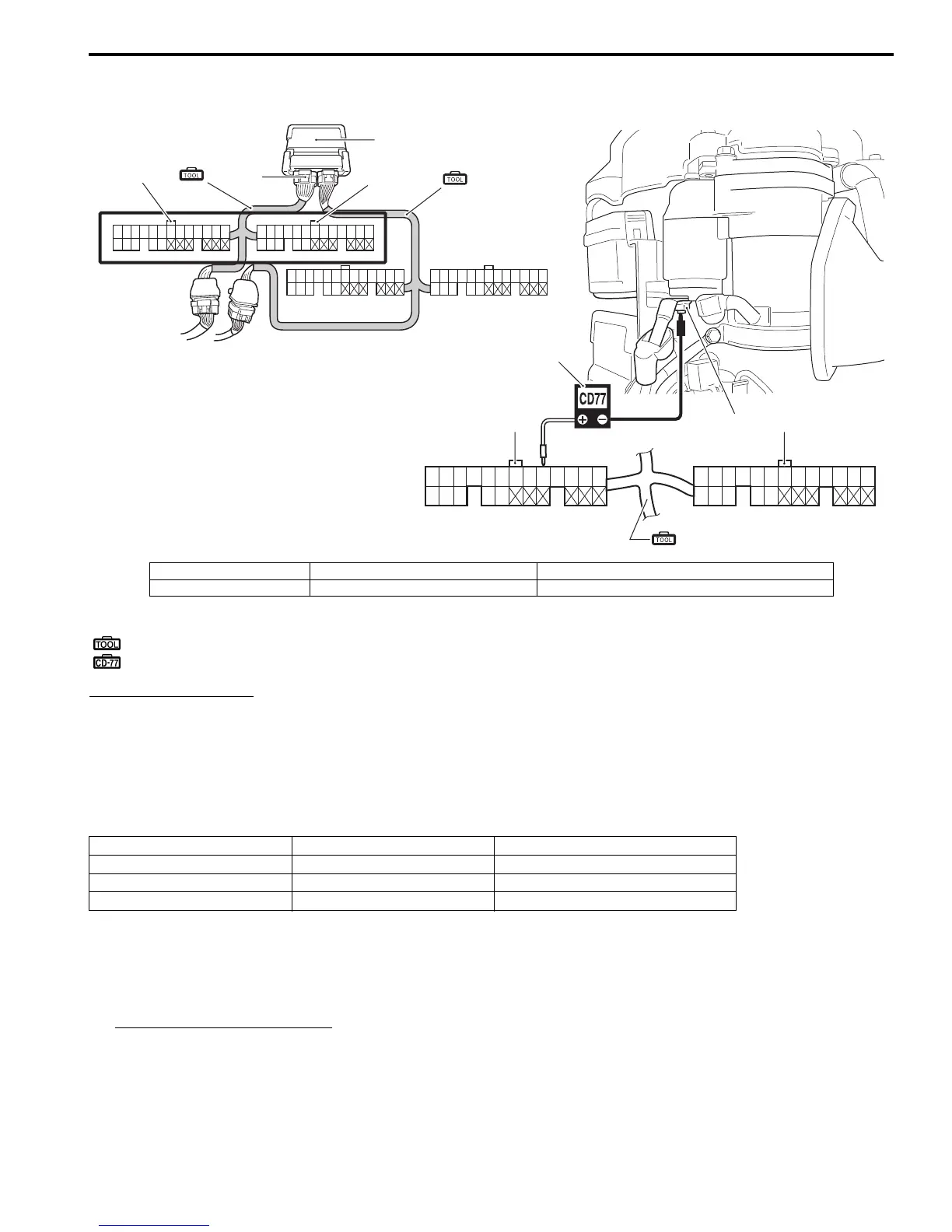
Fuel Injector Operating Signal Inspection
ZAJ6111706012
Special tool
(A): 09930–88730 (36-pin test cord set)
: Stevens peak reading voltmeter CD-77
Tester knob indication
NEG 50
1) Disconnect all ignition coil connectors from the ignition coils.
2) Connect the test cord between the ECM and wire harness as shown in figure, then turn ignition switch “ON”.
3) Connect the tester probe (“–”, Black) to the starter motor magnetic switch terminal “B” (connected to battery
positive (+) terminal) as shown in figure.
4) Connect the tester probe (“+”, Red) to each terminal.
5) Crank the engine and measure the voltage.
If out of specification, inspect the related parts as described in “Fuel System Diagnostic Information / Fuel Injection
System Troubleshooting”.
Refer to “Fuel System Diagnosis” (Page 1G-13) and “Fuel Injection System Troubleshooting” (Page 1G-14).
Fuel injector operating signal
Standard: Approx. 4 – 10 V or over
45 47
71
37
50
38
51
39
52
40 41
53
42 43 44 45 46 47 48 49 55
68
56
69
57
70
58 59
71
60 61 62 63 64 65 66 67
19 20 21 22 23 24 25 26 27 28 29 30 3112345678910111213
14 15 16 17 18
32 33 34 35 36
7254
4
ECM
(A)
(A)
3
1
2
1
2
(A)
5
1. Black connector 3. Peak voltmeter stevens CD-77 5. Starter motor magnetic switch “B” terminal
2. White connector 4. Gray test cord connector side
Injector Terminal Wire color (Engine harness)
No.1 45 O/B
No.2 71 B/Br
No.3 47 R/W
 Loading...