1I-1 Starting System:
Power Head
Starting System
General Description
Electric Starter System Description
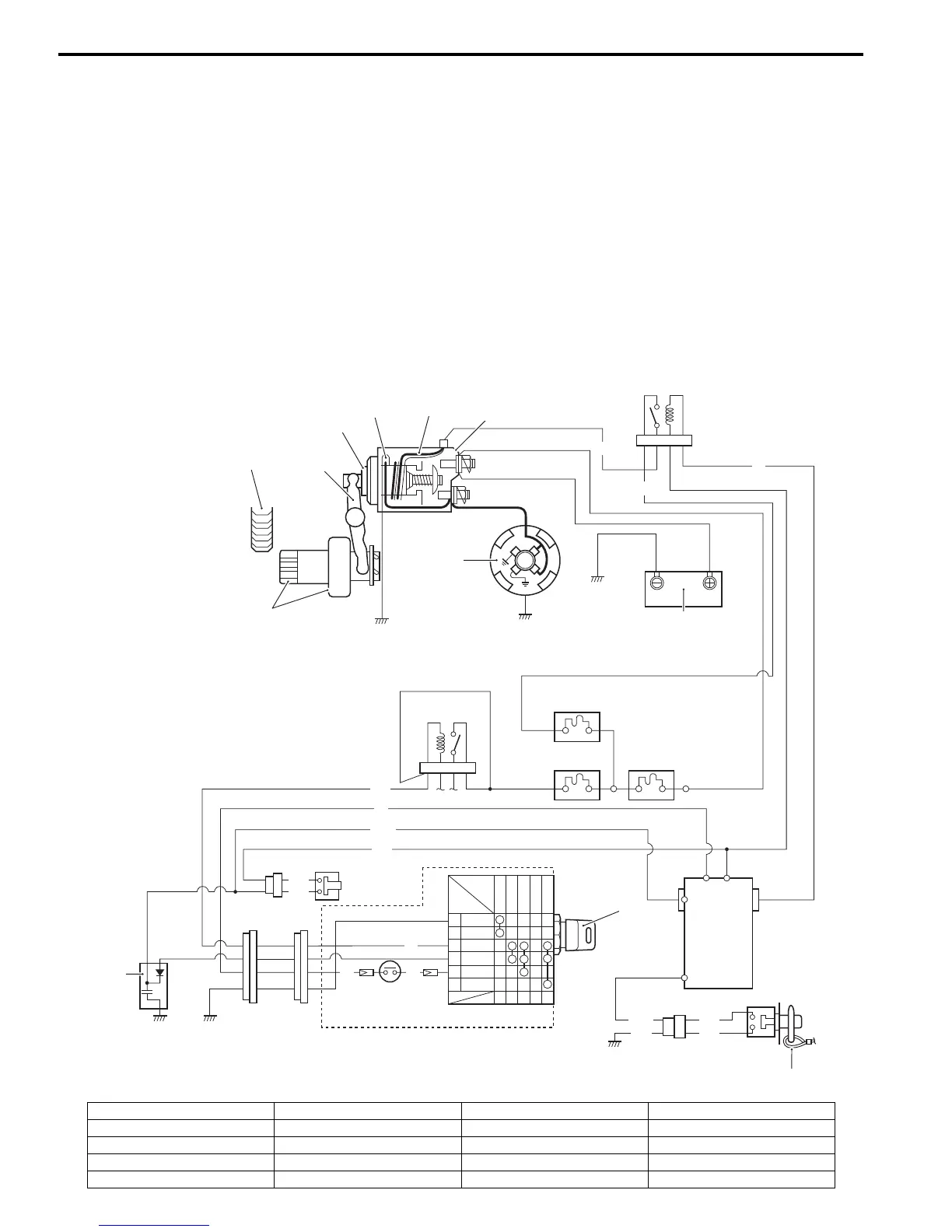
ZAJ6111901001
The starting circuit consists of the battery, starting motor, ignition switch, neutral switch, starter relay, ECM and related
electrical wiring.
These components are connected electrically as shown in the figure below.
In the circuit shown in the figure below, the magnetic switch coils and starter relay coil are magnetized when the
ignition switch is closed (turned to “START”).
The resulting plunger and pinion shift lever movement causes the pinion to engage the engine flywheel gear, the
magnetic switch main contacts to close, and engine cranking to take place.
When the engine starts, the pinion over-running clutch protects the armature from excessive speed until the switch is
opened, at which time the torsion spring causes the pinion to disengage.
16
G
Y/G
Y/G
Br
B
B
BGND
OFF
ON
START
W BATT
Br
START
G
R
ECM
Bl/R
W
1
2
10
3
4
5
6
7
9
8
11
12
13
14
15
17
18
Gr IG
B/Bl
W
W
Br
BrBr
15
1. Starter relay 6. Plunger 11. 30 A Fuse (Starter) 16. Ignition switch
2. Battery 7. Shift lever 12. 30 A Fuse (ECM) 17. Emergency stop switch
3. Magnetic switch 8. Ring gear 13. 30 A Fuse (Main) 18. Capacitor
4. Pull-in coil 9. Starter motor 14. Main relay
5. Hold-in coil 10. Pinion and over-running clutch 15. Neutral switch
 Loading...