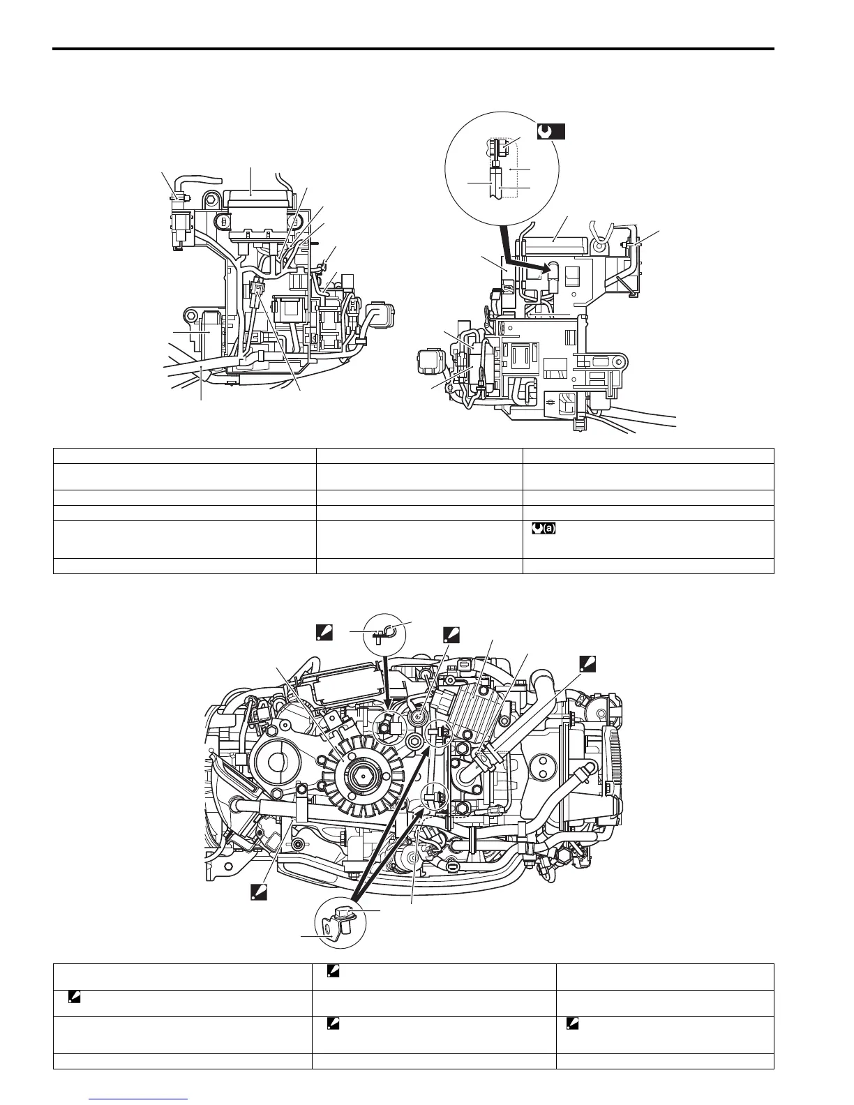
4A-4 Wire Routing:
Wiring Harness Routing Diagram
ZAJ6114102002
10
14
8
9
11
“A”
“B”
12
13
12
11
1
3
2
8
5
6
7
(a)
4
1. Electric parts holder 7. PTT relay lead wire (Red) 13. Main harness GND lead wire
2. PTT relay 8. Cable tie
: Secure the harness with the cable tie.
14. CKP sensor connector
3. PTT relay holder 9. Main harness capacitor “A”: To starter motor magnetic switch “S” terminal
4. Nut 10. Main harness “B”: To starter motor magnetic switch “B” terminal
5. Cap
: Pass the PTT relay lead wire and main harness
red lead wire through the cap.
11. Fuse box : 4.5 N·m (0.45 kgf-m, 3.3 lbf-ft)
6. Main harness (Red) 12. PTT relay lead wire (Red)
1
2
3
5
4
6
7
11
8
10
9
1. Battery charge coil 5. Oil pressure switch
: Cover the oil pressure switch with the cap.
9. Harness bracket
2. Bolt
: Tighten bolt with the rectifier GND lead wire.
6. Cylinder temp. sensor 10. Bolt
3. Clamp 7. Band
: Secure the cylinder temp sensor lead wire
with the band.
11. Throttle position sensor lead wire
: Route the throttle position sensor
lead wire under the breather hose.
4. Rectifier / regulator 8. IAC valve lead wire



 To Next Page