Power Trim and Tilt: 2B-8
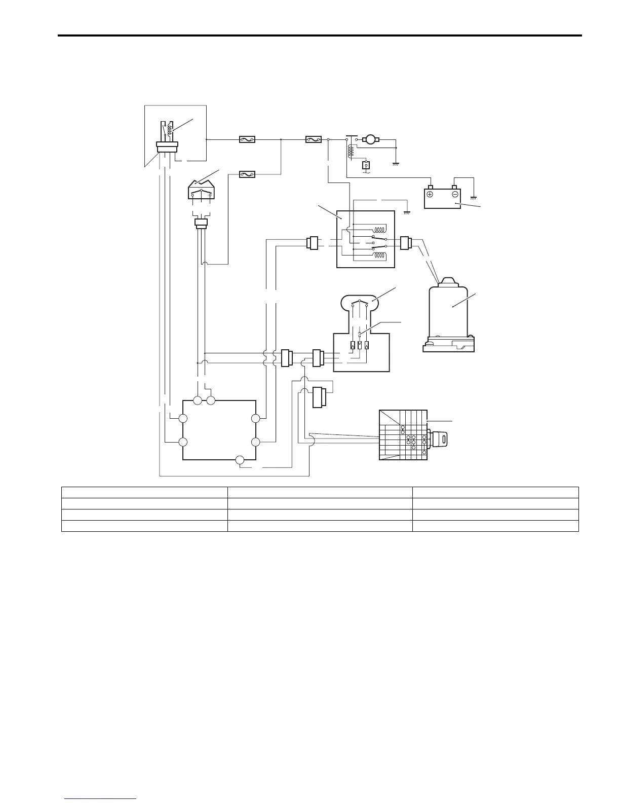
Schematic and Routing Diagram
Power Trim and Tilt System Diagram
ZAJ6112202001
M
BATT
ECM
R
R
Lg
Lbl
Lbl
P
W/R
W/R
Lbl
P
Lbl
B
R
G
B
l
B GND
OFF
ON
START
W BATT
Br START
P/W
Lbl/W
B/G
Lbl
P
W
Gr
P/B
W
Gr
P/B
R
36
3
27
2322
12
35
Gr
IGN
W-tube
10
11
7
3
6
4
1
5
2
P
8
9
1. PTT switch (Remote control box) 5. Ignition switch 9. ECM fuse 30 amp.
2. PTT switch (Side cover) 6. Battery 10. PTT switch fuse 15 amp.
3. PTT motor relay 7. Starter motor 11. Main fuse 30 amp.
4. PTT motor 8. ECM main relay



 To Next Page