1C-7 Engine Electrical Devices:
Component Location
Location of Sensor and Switch
ZAJ6111303001
Refer to “Wiring Harness Routing Diagram” in Section 4A (Page 4A-4).
Service Instructions
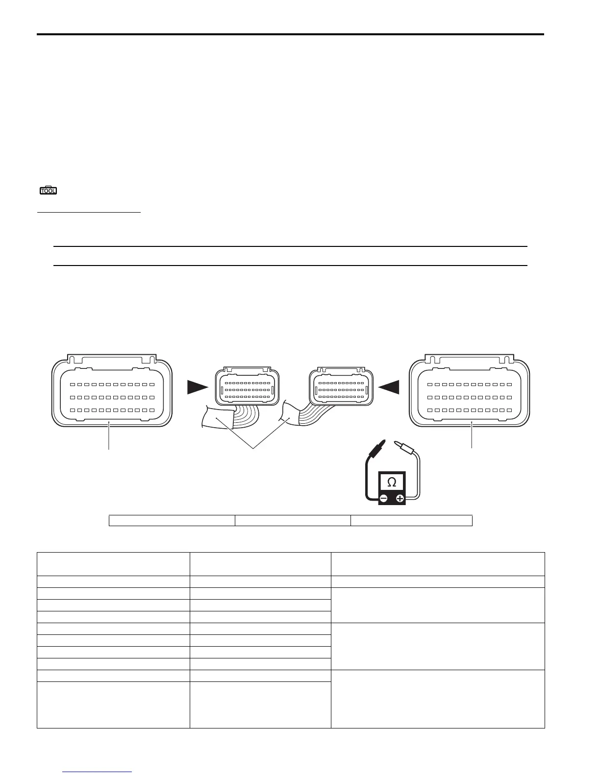
Resistance Check
ZAJ6111306001
Special tool
: 09930–99320 (Digital tester)
Tester knob indication
Resistance (Ω)
NOTE
Make sure ignition switch is always OFF when measuring resistance.
1) Turn ignition switch OFF.
2) Disconnect battery cables from battery.
3) Disconnect wire harness connector from ECM.
4) Connect the tester probes to terminal (wire harness side) and measure resistance according to the “Resistance
Table” (Page 1C-7).
Resistance Table
123456789101112
13 14 15 16 17 18 19 20 21 22 23 24
25 26 27 28 29 30 31 32 33 34 35
36
37 38 39 40 41 42 43 44 45 46 47 48
49 50 51 52 53 54 55 56 57 58 59 60
61 62 63 64 65 66 67 68 69 70 71 72
1
2
3
1. Engine main wire harness 2. Black connector 3. Gray connector
Circuit
Terminal for Tester Probe
Connection
Standard Resistance (at 20 °C)
CKP sensor 50 (R/B) to 25 (B/W) 168 – 252 Ω
Fuel injector No. 1 45 (O/B) to 12 (Gr)
10 – 14 ΩFuel injector No. 2 71 (B/Br) to 12 (Gr)
Fuel injector No. 3 47 (R/W) to 12 (Gr)
IAC Valve #1 60 (W/B) to 12 (Gr)
25 – 34 Ω
IAC Valve #2 70 (R/Y) to 12 (Gr)
IAC Valve #3 58 (R/G) to 12 (Gr)
IAC Valve #4 48 (W/Bl) to 12 (Gr)
IAT sensor 8 (Lg/B) to 25 (B/W) 0 °C (32 °F): 5.3 – 6.6 kΩ
25 °C (77 °F): 1.8 – 2.3 kΩ
50 °C (122 °F): 0.73 – 0.96 kΩ
75 °C (135 °F): 0.33 – 0.45 kΩ
(Thermistor characteristic)
Cylinder temperature sensor 20 (Lg/W) to 25 (B/W)