1G-14 Fuel System:
Fuel Injection System Troubleshooting
ZAJ6111704003
Before starting the troubleshooting, make sure that:
• There is no self-diagnostic code indication.
• Emergency stop switch plate is set in place.
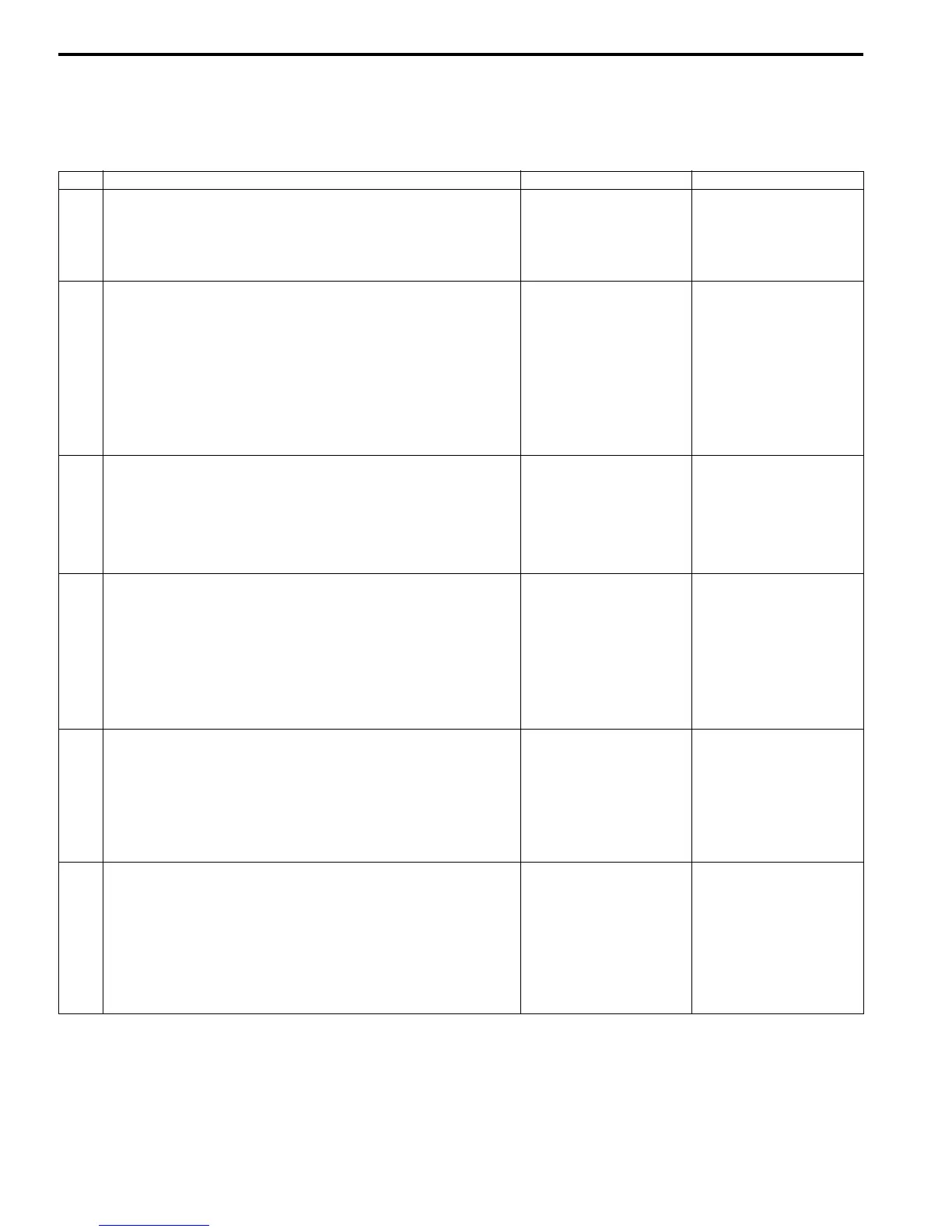
Step Action Yes No
1 Check fuel injector operating sound.
• Check each injector for operating sound at engine
cranking. ()(Page 1G-22))
Do all 3 injector make operating sound?
Fuel injector circuit is in
good condition.
Go to step 2.
2 Check fuel injector resistance.
• Turn ignition switch off, disconnect connectors from fuel
injectors.
• Check for proper connection to fuel injector at each
terminal.
• If good condition, check all fuel injector for resistance.
()(Page 1G-22))
Are all injectors in good condition?
Go to step 3. Faulty fuel injector.
3 Check fuel injector power supply.
• Measure voltage between each “Gray” wire terminal of
fuel injector connector and engine body ground with
ignition switch turned “ON”.
Is voltage 10 – 14 V?
Go to step 4. • “Gray” wire open or
shorted.
• If it is in good
condition, check ECM
power source and
ground circuit.
4 Check Wire circuit.
• Turn “OFF” ignition switch.
• Disconnect connector from ECM.
• Measure resistance between each “O/B”, “B/Br”, “R/W”
wire terminal of the fuel injector connector and body
ground.
Is resistance infinity?
Go to step 5. “O/B”, “B/Br” and/or “R/
W” wire(s) are shorted
to ground.
5 Check Wire circuit.
• Connect connector to ECM.
• Measure voltage between each “O/B”, “B/Br”, “R/W” wire
terminal of fuel injector connector and body ground with
ignition switch turned “ON”.
Is voltage 0 V?
Go to step 6. “O/B”, “B/Br” and/or “R/
W” wire(s) are shorted
to power supply circuit.
6 Check fuel injector operating signal.
• Connect connectors to each fuel injector and ECM with
ignition switch turned “OFF”.
• Measure fuel injector operating signal between each “45”,
“71”, “47” terminal of ECM and body ground. ()(Page
1G-23))
Is voltage 4 – 10 V or over?
If check result is
satisfactory, substitute a
known-good ECM and
recheck.
“O/B”, “B/Br” and/or “R/
W” wire(s) are open
circuit.